-
-
send us mail
[email protected]
The number is indicative of the nominal pressure in bars. In the instance of DIN 2501 PN10 Flange, the Pressure Nominale or simply known as PN is 10 bar. Similar to most standards specifications like the ASTM or EN, the DIN standards have a set of parameters to be met by the manufacturer. In addition to the DIN 2501 PN10 Plate Flange Dimensions, these flanges are required to meet the pressure-temperature ratings, materials, marking, testing, tolerances, as well as the different methods that can be used to designate the openings for pipe flanges and flanged fittings.
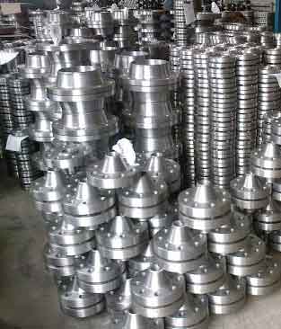
DIN standards always have the pressure rating mentioned next to it as the PN followed by a number.
Although there are several different types of flanges, most buyers across different industries prefer using a DIN 2501 PN10 Slip On Flange over a weld neck type flange for its low cost. However, one has to note that the cost of the flange would depend on the alloy chosen by the buyer. For instance, a carbon steel slip on flange would cost much lower in comparison to a slip on type Stainless Steel DIN 2501 pn10 flange. The material used to build these flanges would be an alloy which has the ability to meet the demands of the application. Which is why alloys such as Monel, Nickel, Inconel, Incoloy, Hastalloy, Titanium, Stainless Steel, Carbon Steel, Duplex Steel as well as Alloy Steel are used as Din 2501 Flange Material during production. Flat Flange Dins 2501 pn10 is well suited to be used for applications involving low and pressure and temperature environments.
| Specification : | DIN 2501 PN10 Flange |
| Coating Flanges Faces : | Cold and Hot Dip Galvanized, Yellow Transparent, Zinc Plated, Oil Black Paint, Anti-rust Paint |
| Design For Size: | BS, DIN, ANSI, ASME, EN, ASA, JIS |
| Pressure Rating Table: | Class 150 LBS, Class 300 LBS, Class 600 LBS, Class 900 LBS, Class 1500 LBS, Class 2500 LBS |
| Standard : | BS10 Flange, DIN Flange, ASME B16.47 (Series A, Series B) Flange, UNI Flange, ASME B16.38 Flange, ISO Flange, JIS Flange, MSS SP44 Flange, EN-1092 Flange, ASME B16.5 Flange, AWWA Flange, GOST Flange |
| Machining Equipment: | Press machine, Pushing Machine, Electric bevelling machine, Bending machine, Sand-blasting machine etc |
| Application: | Chemical Industry Water Pipeline Industry Natural Gas Industry Fabrication Industry Nuclear Power Plant Oil And Gas Industry |
| Supporting Flanges Material: | Ring Joint, Flanges Bolts, Gasket |
| Connect Type Type: | LMF, RF, LJF, FF, RTJ, SMF |
| Size Chart : | 1/2″ (15 NB) To 48″ (1200NB) |
| Common Types of Flanges Dimensions: | Class 150 RTJ Flanges 300 LB WNRF Class 900 SORF 1500# BLRF Class 2500 BLRF |
| Production Process: | Forged, Heat Treated and Machined |
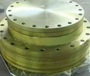
DIN 2501 PN10 Plate Flange
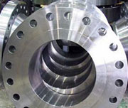
DIN 2501 PN10 Slip On Flange
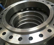
Din 2501 Flange Material
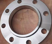
Flat Flange Din 2501 pn10
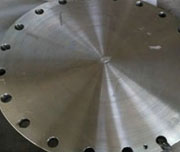
Flanges Norma DIN 2576 PN10
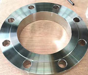
DIN 2576 PN 10 Form B Flange
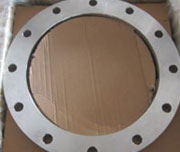
DIN 2576 PN 10 DN 300 Flange
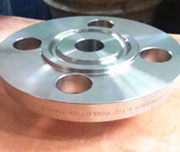
DIN 2501 PN10 Blind Flange
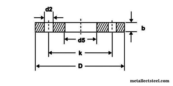
| NPS | Diam. of | Flanges Diameter | Flanges I.D | Thickness of Flanges | Diameter of Bolt Cirlce | Number of | Diameter of Bolt Holes | Weight | |
|---|---|---|---|---|---|---|---|---|---|
| PLATE | BLIND | ||||||||
| DN | Pipe | D | D5 | B | K | holes | D2 | KG | KG |
| 15 | 21.30 | 95 | 22.00 | 14 | 65 | 4 | 14 | 0.67 | 0.71 |
| 20 | 26.90 | 105 | 27.60 | 16 | 75 | 4 | 14 | 0.93 | 1.01 |
| 25 | 33.70 | 115 | 34.40 | 16 | 85 | 4 | 14 | 1.11 | 1.23 |
| 32 | 42.40 | 140 | 43.10 | 16 | 100 | 4 | 18 | 1.62 | 1.81 |
| 40 | 48.30 | 150 | 49.00 | 16 | 110 | 4 | 18 | 1.85 | 2.09 |
| 50 | 60.30 | 165 | 61.10 | 18 | 125 | 4 | 18 | 2.46 | 2.88 |
| 65 | 76.10 | 185 | 77.10 | 18 | 145 | 4 | 18 | 2.99 | 3.65 |
| 80 | 88.90 | 200 | 90.30 | 20 | 160 | 8 | 18 | 3.61 | 4.61 |
| 100 | 114.30 | 220 | 115.90 | 20 | 180 | 8 | 18 | 3.99 | 5.65 |
| 125 | 139.70 | 250 | 141.60 | 22 | 210 | 8 | 18 | 5.41 | 8.13 |
| 150 | 168.30 | 285 | 170.50 | 22 | 240 | 8 | 22 | 6.55 | 10.44 |
| 175 | 193.70 | 315 | 196.10 | 24 | 270 | 8 | 22 | 8.42 | |
| 200 | 219.10 | 340 | 221.80 | 24 | 295 | 12 | 22 | 8.97 | 16.48 |
| 250 | 273.00 | 405 | 276.20 | 26 | 355 | 12 | 26 | 12.76 | 23.99 |
| 300 | 323.90 | 460 | 327.60 | 28 | 410 | 12 | 26 | 16.60 | 30.73 |
| 350 | 355.60 | 520 | 359.70 | 30 | 470 | 16 | 26 | 24.08 | 42.56 |
| 400 | 406.40 | 580 | 411.00 | 32 | 525 | 16 | 30 | 30.20 | 60.68 |
| 450 | 457.00 | 640 | 462.30 | 38 | 585 | 20 | 30 | 41.67 | 71.74 |
| 500 | 508.00 | 715 | 513.60 | 38 | 650 | 20 | 33 | 52.87 | 96.4 |
| 600 | 610.00 | 840 | 616.50 | 42 | 770 | 20 | 36 | 77.58 | 145.6 |
| 700 | 711.00 | 910 | 716.00 | 44 | 840 | 24 | 36 | 77.13 | |
| 800 | 813.00 | 1025 | 818.00 | 50 | 950 | 24 | 39 | 106.35 | |
| 900 | 914.00 | 1125 | 920.00 | 54 | 1050 | 28 | 39 | 125.39 | |
| 1000 | 1016.00 | 1255 | 1022.00 | 60 | 1170 | 28 | 42 | 177.99 | |
| Temperature (in F°) | Class 150 | Class 300 | Class 400 | Class 600 | Class 900 | Class 1500 | Class 2500 |
| < 100 | 285 | 740 | 985 | 1480 | 2220 | 3705 | 6170 |
| 200 | 260 | 680 | 905 | 1360 | 2035 | 3395 | 5655 |
| 300 | 230 | 655 | 870 | 1310 | 1965 | 3270 | 5450 |
| 400 | 200 | 635 | 845 | 1265 | 1900 | 3170 | 5280 |
| 500 | 170 | 605 | 805 | 1205 | 1810 | 3015 | 5025 |
| 600 | 140 | 570 | 755 | 1135 | 1705 | 2840 | 4730 |
| 650 | 125 | 550 | 730 | 1100 | 1650 | 2745 | 4575 |
| 700 | 110 | 530 | 710 | 1060 | 1590 | 2655 | 4425 |
| 750 | 95 | 505 | 675 | 1015 | 1520 | 2535 | 4230 |
| 800 | 80 | 410 | 550 | 825 | 1235 | 2055 | 3430 |
| 850 | 65 | 320 | 425 | 640 | 955 | 1595 | 2655 |
| 900 | 50 | 230 | 305 | 460 | 690 | 1150 | 1915 |
| 950 | 35 | 135 | 185 | 275 | 410 | 685 | 1145 |
| 1000 | 20 | 85 | 115 | 170 | 255 | 430 | 715 |
| Hydrostatic Test (psig) | 450 | 1125 | 1500 | 2225 | 3350 | 5575 | 9275 |
| NPS NPS (inch) |
|||||
|---|---|---|---|---|---|
| Diammeter of Flanges (inch) |
No. of Bolts |
Diammeter of Bolts (inch) |
Diammeter of Bolt Holes (inch) |
Bolt Circle (inch) |
|
| 1/4 | 3-3/8 | 4 | 1/2 | 0.62 | 2-1/4 |
| 1/2 | 3-1/2 | 4 | 1/2 | 0.62 | 2-3/8 |
| 3/4 | 3-7/8 | 4 | 1/2 | 0.62 | 2-3/4 |
| 1 | 4-1/4 | 4 | 1/2 | 0.62 | 3-1/8 |
| 1-1/4 | 4-5/8 | 4 | 1/2 | 0.62 | 3-1/2 |
| 1-1/2 | 5 | 4 | 1/2 | 0.62 | 3-7/8 |
| 2 | 6 | 4 | 5/8 | 0.75 | 4-3/4 |
| 2-1/2 | 7 | 4 | 5/8 | 0.75 | 5-1/2 |
| 3 | 7-1/2 | 4 | 5/8 | 0.75 | 6 |
| 3-1/2 | 8-1/2 | 8 | 5/8 | 0.75 | 7 |
| 4 | 9 | 8 | 5/8 | 0.75 | 7-1/2 |
| 5 | 10 | 8 | 3/4 | 0.88 | 8-1/2 |
| 6 | 11 | 8 | 3/4 | 0.88 | 9-1/2 |
| 8 | 13-1/2 | 8 | 3/4 | 0.88 | 11-3/4 |
| 10 | 16 | 12 | 7/8 | 1 | 14-1/4 |
| 12 | 19 | 12 | 7/8 | 1 | 17 |
| 14 | 21 | 12 | 1 | 1.12 | 18-3/4 |
| 16 | 23-1/2 | 16 | 1 | 1.12 | 21-1/4 |
| 18 | 25 | 16 | 1-1/8 | 1.25 | 22-3/4 |
| 20 | 27-1/2 | 20 | 1-1/8 | 1.25 | 25 |
| 24 | 32 | 20 | 1-1/4 | 1.38 | 29-1/2 |