-
-
send us mail
[email protected]
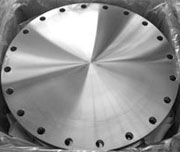
Blind Flanges are characteristically produced without a bore. This is why a blind flange could be used across piping systems to blank off or seal off the ends of piping, Valves and pressure vessel openings. The ASME B16.5 Blind Flange is frequently produced from forged, cast, or plate materials.
From the standpoint of internal pressure and bolt loading, a 4 inch Slip On Blind Flange, particularly those manufactured in the larger sizes, tend to be the most highly stressed type of flanges.
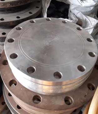
Purchase Blind Flanges, 2 x 4 Inch To 8 x 4 inch, 150#, 300#, RF, Forged Schedule 10 * Schedule 120, Material ASTM A105 & ASTM A182, ASME B16.5 At Best Price.
However, most of these stress or load are the bending type near the centre. And since there is no standard inside diameter, the ANSI B16.5 Threaded Blind Flange is well suited to be used for higher pressure temperature applications. Apart from several aspects covered by this standard such as pressure-temperature ratings, materials, Carbon Steel BLRF Flange Dimensions, tolerances, marking, testing, and methods of designating openings; the ASME B16.5 also takes into account requirements and recommendations regarding flanges gaskets, flanges bolting, and flanges joints. The Raised Face Blind Flange Pressure Ratinge is designated in the following classes i.e. 150, 300, 400, 600, 900, 1500, and 2500. Whereas the Stainless Steel Blind Flange is produced in sizes NPS 1/2 through NPS 24, with the requirements of these flanges mentioned in both metric and U.S units.
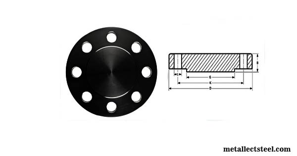
| NPS | "A" (Outer Diameter) |
"B" (Thickness) |
"C" (RF Diameter.) |
"D" (B.C.D.) |
# Bolt Holes |
Dia. of Bolt Holes |
Approx. Weight |
|---|---|---|---|---|---|---|---|
| 1/2" | 3-1/2 | 7/16 | 1-3/8 | 2-3/8 | 4 | 5/8 | 2 |
| 3/4" | 3-7/8 | 1/2 | 1-11/16 | 2-3/4 | 4 | 5/8 | 2 |
| 1" | 4-1/4 | 9/16 | 2 | 3-1/8 | 4 | 5/8 | 2 |
| 1-1/4" | 4-5/8 | 5/8 | 2-1/2 | 3-1/2 | 4 | 5/8 | 3 |
| 1-1/2" | 5 | 11/16 | 2-7/8 | 3-7/8 | 4 | 5/8 | 3 |
| 2" | 6 | 3/4 | 3-5/8 | 4-3/4 | 4 | 3/4 | 4 |
| 2-1/2" | 7 | 7/8 | 4-1/8 | 5-1/2 | 4 | 3/4 | 7 |
| 3" | 7-1/2 | 15/16 | 5 | 6 | 4 | 3/4 | 9 |
| 3-1/2" | 8-1/2 | 15/16 | 5-1/2 | 7 | 8 | 3/4 | 13 |
| 4" | 9 | 15/16 | 6-3/16 | 7-1/2 | 8 | 3/4 | 17 |
| 5" | 10 | 15/16 | 7-5/16 | 8-1/2 | 8 | 7/8 | 20 |
| 6" | 11 | 1 | 8-1/2 | 9-1/2 | 8 | 7/8 | 27 |
| 8" | 13-1/2 | 1-1/8 | 10-5/8 | 11-3/4 | 8 | 7/8 | 47 |
| 10" | 16 | 1-3/16 | 12-3/4 | 14-1/4 | 12 | 1 | 67 |
| 12" | 19 | 1-1/4 | 15 | 17 | 12 | 1 | 123 |
| 14" | 21 | 1-3/8 | 16-1/4 | 18-3/4 | 12 | 1-1/8 | 139 |
| 16" | 23-1/2 | 1-7/16 | 18-1/2 | 21-1/4 | 16 | 1-1/8 | 187 |
| 18" | 25 | 1-9/16 | 21 | 22-3/4 | 16 | 1-1/4 | 217 |
| 20" | 27-1/2 | 1-11/16 | 23 | 25 | 20 | 1-1/4 | 283 |
| 24" | 32 | 1-7/8 | 27-1/4 | 29-1/2 | 20 | 1-3/8 | 415 |
| Specification : | ASME B16.5 Blind Flange |
| Machining Equipment: | Bending machine, Pushing Machine, Sand-blasting machine, Press machine, electric bevelling machine etc |
| Production Process: | Forged, Heat Treated and Machined |
| Design For Size: | ASA, ASME, DIN, PN, JIS, ANSI, BS, EN |
| ASME B16.5 Application: | Oil And Gas Industry Chemical Industry Natural Gas Industry Water Pipeline Industry Fabrication Industry Nuclear Power Plant |
| Connect Type Type: | RF, FF, RTJ, LMF, SMF, LJF. |
| Pressure Rating Table: | Class 150 LBS, Class 300 LBS, Class 600 LBS, Class 900 LBS, Class 1500 LBS, Class 2500 LBS |
| Coating Faces : | Yellow Transparent, Oil Black Paint, Anti-rust Paint, Cold and Hot Dip Galvanized, Zinc Plated |
| ASA Flange Size Chart : | 1/2″ (15 NB) To 48″ (1200NB) |
| Standards : | ASME B16.5, ASME B16.47 (Series A, Series B), ASME B16.38, EN-1092, BS10, DIN, PN, JIS, ISO, GOST, UNI, AWWA, MSS SP44. |
| Pressure Ratings Of ASME B16.5 Blind Flange With Weight and Size | ||||||||||||||||||
| NPS | 150 LBS | 300 LBS | 600 LBS | 900 LBS | 1500 LBS | 2500 LBS | ||||||||||||
| WN | SO | BLD | WN | SO | BLD | WN | SO | BLD | WN | SO | BLD | WN | SO | BLD | WN | SO | BLD | |
| 1/2" | 2 | 1 | 1 | 2 | 1 | 1 | 2 | 2 | 2 | 1500 # WEIGHTS | 5 | 4 | 4 | 7 | 7 | 7 | ||
| 3/4" | 2 | 2 | 2 | 3 | 3 | 3 | 4 | 3 | 3 | 1500 # WEIGHTS | 6 | 5 | 6 | 8 | 8 | 8 | ||
| 1" | 3 | 2 | 2 | 4 | 3 | 3 | 4 | 4 | 4 | 1500 # WEIGHTS | 9 | 8 | 8 | 12 | 11 | 11 | ||
| 1 1/2" | 4 | 3 | 3 | 7 | 6 | 6 | 8 | 7 | 8 | 1500 # WEIGHTS | 13 | 12 | 13 | 25 | 22 | 23 | ||
| 2" | 6 | 5 | 5 | 9 | 7 | 8 | 12 | 9 | 10 | 1500 # WEIGHTS | 25 | 25 | 25 | 42 | 37 | 39 | ||
| 2 1/2" | 8 | 7 | 7 | 12 | 10 | 12 | 18 | 13 | 15 | 1500 # WEIGHTS | 36 | 36 | 35 | 52 | 55 | 56 | ||
| 3" | 10 | 8 | 9 | 15 | 13 | 16 | 23 | 16 | 20 | 31 | 26 | 29 | 48 | 48 | 48 | 94 | 83 | 86 |
| 4" | 15 | 13 | 17 | 25 | 22 | 27 | 42 | 37 | 41 | 53 | 53 | 54 | 73 | 73 | 73 | 145 | 125 | 130 |
| 5" | 19 | 15 | 20 | 32 | 28 | 35 | 68 | 63 | 68 | 86 | 83 | 87 | 130 | 130 | 140 | 245 | 210 | 225 |
| 6" | 24 | 19 | 26 | 42 | 39 | 50 | 81 | 80 | 86 | 110 | 110 | 115 | 165 | 165 | 160 | 380 | 325 | 345 |
| 8" | 39 | 30 | 45 | 67 | 58 | 81 | 120 | 115 | 140 | 175 | 170 | 200 | 275 | 260 | 300 | 580 | 485 | 530 |
| 10" | 52 | 43 | 70 | 91 | 81 | 124 | 190 | 170 | 230 | 260 | 245 | 290 | 455 | 435 | 510 | 1075 | 930 | 1025 |
| 12" | 80 | 64 | 110 | 140 | 115 | 185 | 225 | 200 | 295 | 325 | 325 | 415 | 690 | 580 | 690 | 1525 | 1100 | 1300 |
| 14" | 110 | 90 | 140 | 180 | 165 | 250 | 280 | 230 | 355 | 400 | 400 | 520 | 940 | NA | 975 | NA | NA | NA |
| 16" | 140 | 98 | 180 | 250 | 190 | 295 | 390 | 330 | 495 | 495 | 425 | 600 | 1250 | NA | 1300 | NA | NA | NA |
| 18" | 150 | 130 | 220 | 320 | 250 | 395 | 475 | 400 | 630 | 680 | 600 | 850 | 1625 | NA | 1750 | NA | NA | NA |
| 20" | 180 | 165 | 285 | 400 | 315 | 505 | 590 | 510 | 810 | 830 | 730 | 1075 | 2050 | NA | 2225 | NA | NA | NA |
| 22" | 225 | 185 | 355 | 465 | 370 | 640 | 720 | 590 | 1000 | NA | NA | NA | NA | NA | NA | NA | NA | NA |
| 24" | 260 | 220 | 430 | 580 | 475 | 790 | 830 | 730 | 1250 | 1500 | 1400 | 2025 | 3325 | NA | 3625 | NA | NA | NA |
| Conversion Data | ||||
| • 1 in. = 25.44 millimeter | • 1 millimeter = 0.03937 in. | • 1 lb/ft^2 = 47.88 Pa | • 1 psi = 6.8948 Pa | • x°F = (5/9)(x-32)°C |
| • 1 pound = 0.45359 Kilogram | • 1 Kilogram = 2.20462 pounds | • 1 Pa = 0.020885 lb/ft^2 | • 1 Pa = 0.00014504 psi | • x°C = (9/5)x + 32°F |
150# BLRF 2 304 Blind Pipe Flange
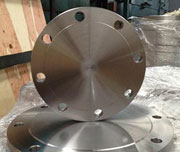
BS4504 304 Stainless Steel Raised Face Blind Flange
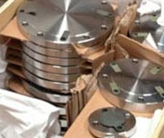
ANSI B16.5 Rating Class 150 Rf Blind Flange
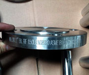
BS4504 ISO 9001 Standard Threaded Blind Flange
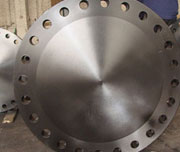
ASTM 8' 600LB SCH40S Ductile Iron Blind Flange
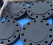
Forged Carbon Steel 6 Inch Blind Flange
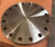
ANSI B16.5 300LBS A105 Flat Face Blind Flange
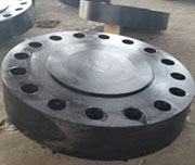
2 inch 900# Table E Blind Flange
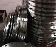
2 Inch To 24 Inch Aluminum Blind Flange

1/2 in. 300# A105 Grooved Blrf Flange
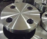
High Pressure ASTM A105 Din 50 High Hub Blind Flange
Low Temp 1 1/2 Rf 600# Copper Blind Flange
| NPS | "A" (Outer Diameter) |
"B" (Thickness) |
"C" (RF Diameter.) |
"D" (B.C.D.) |
# Bolt Holes |
Diameter of Bolt Holes |
Approx. Weight |
|---|---|---|---|---|---|---|---|
| 1/2" | 3-3/4 | 9/16 | 1-3/8 | 2-5/8 | 4 | 5/8 | 2 |
| 3/4" | 4-5/8 | 5/8 | 1-11/16 | 3-1/4 | 4 | 3/4 | 3 |
| 1" | 4-7/8 | 11/16 | 2 | 3-1/2 | 4 | 3/4 | 4 |
| 1-1/4" | 5-1/4 | 3/4 | 2-1/2 | 3-7/8 | 4 | 3/4 | 6 |
| 1-1/2" | 6-1/8 | 13/16 | 2-7/8 | 4-1/2 | 4 | 7/8 | 7 |
| 2" | 6-1/2 | 7/8 | 3-5/8 | 5 | 8 | 3/4 | 8 |
| 2-1/2" | 7-1/2 | 1 | 4-1/8 | 5-7/8 | 8 | 7/8 | 12 |
| 3" | 8-1/4 | 1-1/8 | 5 | 6-5/8 | 8 | 7/8 | 16 |
| 3-1/2" | 9 | 1-3/16 | 5-1/2 | 7-1/4 | 8 | 7/8 | 21 |
| 4" | 10 | 1-1/4 | 6-3/16 | 7-7/8 | 8 | 7/8 | 28 |
| 5" | 11 | 1-3/8 | 7-5/16 | 9-1/4 | 8 | 7/8 | 37 |
| 6" | 12-1/2 | 1-7/16 | 8-1/2 | 10-5/8 | 12 | 7/8 | 48 |
| 8" | 15 | 1-5/8 | 10-5/8 | 13 | 12 | 1 | 79 |
| 10" | 17-1/2 | 1-7/8 | 12-3/4 | 15-1/4 | 16 | 1-1/8 | 122 |
| 12" | 20-1/2 | 2 | 15 | 17-3/4 | 16 | 1-1/4 | 183 |
| 14" | 23 | 2-1/8 | 16-1/4 | 20-1/4 | 20 | 1-1/4 | 241 |
| 16" | 25-1/2 | 2-1/4 | 18-1/2 | 22-1/2 | 20 | 1-3/8 | 315 |
| 18" | 28 | 2-3/8 | 21 | 24-3/4 | 24 | 1-3/8 | 414 |
| 20" | 30-1/2 | 2-1/2 | 23 | 27 | 24 | 1-3/8 | 515 |
| 24" | 36 | 2-3/4 | 27-1/4 | 32 | 24 | 1-5/8 | 800 |
| ASME/ ANSI / ASA B16.5 Class 600 Blind Flange-RF | |||||||
|---|---|---|---|---|---|---|---|
| ø | D | b | g | k | Holes | l | Kg. |
| 1/2" | 95,2 | 14,3 | 34,9 | 66,7 | 4 | 15,9 | 0,700 |
| 3/4" | 117,5 | 15,9 | 42,9 | 82,5 | 4 | 19,0 | 1,200 |
| 1" | 123,8 | 17,5 | 50,8 | 88,9 | 4 | 19,0 | 1,500 |
| 1 1/4" | 133,3 | 20,6 | 63,5 | 98,4 | 4 | 19,0 | 2,000 |
| 1 1/2" | 155,6 | 22,2 | 73,0 | 114,3 | 4 | 22,2 | 3,200 |
| 2" | 165,1 | 25,4 | 92,1 | 127,0 | 8 | 19,0 | 4,300 |
| 2 1/2" | 190,5 | 28,6 | 104,8 | 149,2 | 8 | 22,2 | 6,000 |
| 3" | 209,5 | 31,7 | 127,0 | 168,3 | 8 | 22,2 | 8,000 |
| 3 1/2" | 228,6 | 34,9 | 139,7 | 184,1 | 8 | 25,4 | 10,500 |
| 4" | 273,0 | 38,1 | 157,2 | 215,9 | 8 | 25,4 | 18,000 |
| 5" | 330,2 | 44,4 | 185,7 | 266,7 | 8 | 28,6 | 28,500 |
| 6" | 355,6 | 47,6 | 215,9 | 292,1 | 12 | 28,6 | 35,500 |
| 8" | 419,1 | 55,6 | 269,9 | 349,2 | 12 | 31,7 | 58,000 |
| 10" | 508,0 | 63,5 | 323,8 | 431,8 | 16 | 34,9 | 98,000 |
| 12" | 558,8 | 66,7 | 381,0 | 488,9 | 20 | 34,9 | 125,000 |
| 14" | 603,2 | 69,8 | 412,7 | 527,0 | 20 | 38,1 | 151,000 |
| 16" | 685,8 | 76,2 | 469,9 | 603,2 | 20 | 41,3 | 215,000 |
| 18" | 742,9 | 82,5 | 533,4 | 654,0 | 20 | 44,4 | 287,000 |
| 20" | 812,8 | 88,9 | 584,2 | 723,9 | 24 | 44,4 | 366,000 |
| 22" | 869,9 | 95,2 | 641,2 | 777,9 | 24 | 47,6 | 437,000 |
| 24" | 939,8 | 101,6 | 692,1 | 838,2 | 24 | 50,8 | 532,000 |
| Pipe Normal Diameter. | Outer Diameter Flange | Thickness Of Flange Min | Diameter of Hub | Diameter of Bolt Circle | Diameter of Bolt Holes | Number of Bolts | Diameter of Bolts(in.) | Approx. Weight | ||
|---|---|---|---|---|---|---|---|---|---|---|
| in. | dn | O | C | X | BC | BH | BN | BD | KG/PCS | LB/PCS |
| 1/2 | 15 | 120.7 | 22.4 | 38.1 | 82.6 | 22.4 | 4 | 3/4 | 1.9 | 4.2 |
| 3/4 | 20 | 130 | 25.4 | 44.5 | 88.9 | 22.4 | 4 | 3/4 | 2.7 | 6 |
| 1 | 25 | 149.4 | 28.4 | 52.3 | 101.6 | 25.4 | 4 | 7/8 | 3.7 | 8.1 |
| 1-1/4 | 32 | 158.8 | 28.4 | 63.5 | 111.3 | 25.4 | 4 | 7/8 | 4.3 | 9.5 |
| 1-1/2 | 40 | 177.8 | 31.8 | 69.9 | 124 | 28.4 | 4 | 1 | 5.9 | 13 |
| 2 | 50 | 215.9 | 38.1 | 104.6 | 165.1 | 25.4 | 8 | 7/8 | 11.3 | 24.9 |
| 2-1/2 | 65 | 244.3 | 41.1 | 124 | 190.5 | 28.4 | 8 | 1 | 16 | 35.2 |
| 3 | 80 | 266.7 | 47.8 | 133.4 | 190.5 | 25.4 | 8 | 7/8 | 19.5 | 43 |
| 4 | 100 | 311.2 | 53.8 | 162.1 | 235 | 31.8 | 8 | 1 1/8 | 33 | 72.8 |
| 5 | 125 | 374.7 | 73.2 | 196.9 | 279.4 | 35.1 | 8 | 1 1/4 | 60 | 132 |
| 6 | 150 | 393.7 | 82.6 | 228.6 | 317.5 | 31.8 | 12 | 1 1/8 | 75 | 165 |
| 8 | 200 | 482.6 | 91.9 | 292.1 | 393.7 | 38.1 | 12 | 1 3/8 | 125 | 275 |
| 10 | 250 | 584.2 | 108 | 368.3 | 469.9 | 38.1 | 16 | 1 3/8 | 215 | 474 |
| 12 | 300 | 673.1 | 124 | 450.9 | 533.4 | 38.1 | 20 | 1 3/8 | 316 | 697 |
| 14 | 350 | 749.3 | 133.4 | 495.3 | 558.8 | 41.1 | 20 | 1 1/2 | ||
| 16 | 400 | 825.5 | 146.1 | 552.5 | 616 | 44.5 | 20 | 1 5/8 | ||
| 18 | 450 | 914.4 | 162.1 | 596.9 | 685.8 | 50.8 | 20 | 1 7/8 | ||
| 20 | 500 | 984.3 | 177.8 | 641.4 | 749.3 | 53.8 | 20 | 2 | ||
| 24 | 600 | 1168.4 | 203.2 | 762 | 901.7 | 66.5 | 20 | 2 1/2 | ||
| Pipe Normal Diameter | Outer Diameter Flange | Thk. Of Flange Min | Diameter of Bolt Circle | Diameterof Bolt Holes | Num. of Bolts | Diameter of Bolts(inch) | Kilogram | LB | |
|---|---|---|---|---|---|---|---|---|---|
| in. | dn | O | C | BC | BH | BN | BD | ||
| 1/2 | 15 | 133.4 | 30.2 | 88.9 | 22.4 | 4 | 3/4 | 3 | 7 |
| 3/4 | 20 | 139.7 | 31.8 | 95.3 | 22.4 | 4 | 3/4 | 4.5 | 10 |
| 1 | 25 | 158.8 | 35.1 | 108 | 25.4 | 4 | 7/8 | 5 | 12 |
| 1-1/4 | 32 | 184.2 | 38.1 | 130 | 28.4 | 4 | 1 | 8 | 18 |
| 1-1/2 | 40 | 203.2 | 44.5 | 146.1 | 31.8 | 4 | 1 1/8 | 11 | 25 |
| 2 | 50 | 235 | 50.8 | 171.5 | 28.4 | 8 | 1 | 17 | 38 |
| 2-1/2 | 65 | 266.7 | 57.2 | 196.9 | 31.8 | 8 | 1 1/8 | 25 | 55 |
| 3 | 80 | 304.8 | 66.5 | 228.6 | 35.1 | 8 | 1 1/4 | 39 | 86 |
| 4 | 100 | 355.6 | 76.2 | 273.1 | 41.1 | 8 | 1 1/2 | 60 | 133 |
| 5 | 125 | 419.1 | 91.9 | 323.9 | 47.8 | 8 | 1 3/4 | 101 | 223 |
| 6 | 150 | 482.6 | 108 | 368.3 | 53.8 | 8 | 2 | 156 | 345 |
| 8 | 200 | 552.5 | 127 | 438.2 | 53.8 | 12 | 2 | 242 | 533 |
| 10 | 250 | 673.1 | 165.1 | 539.8 | 66.5 | 12 | 2 1/2 | 465 | 1023 |
| 12 | 300 | 762 | 184.2 | 619.3 | 73.2 | 12 | 2 3/4 | 665 | 1463 |