-
-
send us mail
[email protected]
Generally, this carbon steel or alloy steel ASTM A350 LF2 Flanges are forged in order to improve the mechanical properties, impact resistance and fatigue resistance. The specification mentions three different melting procedure in order to produce these flanges i.e open hearth, electric furnace, basic oxygen, or vacuum-induction melting. In addition to being forged, the materials used to produce the A350 LF2 Welding Neck Flange are to be heat treated along with a heat and product analysis conducted on them. The heat treatment used by manufacturers on the Carbon Steel A350 Lf2 Flanges includes normalizing, tempering, quenching as well as precipitation heat treatment. Grade LF2 under specification ASTM A350, is segregated further into Class 1 and Class 2. Both classes 1 and 2 of the SA350 LF2 WN Flange have the same chemical composition, mechanical properties and allowable stresses.
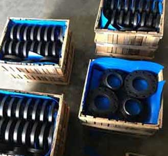
ASTM A350 LF2 Flanges
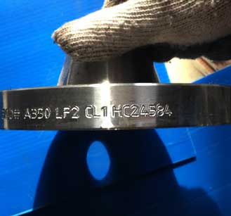
A350 Gr. LF2 CL.1 Blind Flange
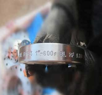
Carbon Steel A350 Lf2 Flanges
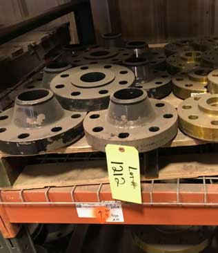
Flanges produced in accordance with the ASTM A350 are designed for low pressure applications.
| Material Group | Common Name | Material Type | UNS | Forging Spec. | Casting Spec. Equivalent | DIN | DIN W. No | Application |
|---|---|---|---|---|---|---|---|---|
| Carbon Steel | CS | C-Si | K03504 | A105 | A216-WCB | C22.8 DIN 17243 | 1.0460 | General non-corrosive service from -29ºC (-20ºF) to 425ºC (800ºF) |
| Low Temperature Carbon Steel | LTCS | C-Mn-Fe | K03011 | A350-LF2 | A352-LCB A352-LCC | TSTE 355 DIN 18103 | 1.0566 | General non-corrosive service from -46ºC (-50ºF) to 340ºC (650ºF), LF2 -46ºC ~ 425ºC |
| Low Temperature Alloy Steel | Nickel Steel | 3.1/2Ni | K32025 | A350-LF3 | A352-LC3 | 10Ni14 | 1.5637 | -101ºC (150ºF) to 340ºC (650ºF) |
The main characteristic that distinguishes A350 Gr. LF2 CL.1 Blind Flange from Class 2 is its minimum applicable temperature. The minimum applicable temperatures are -50°F for LF2 Class 1 flanges and -0°F for LF2 Class 2 flanges, respectively. The minimum applicable temperature for the A350 LF2 Carbon Steel Blind Flanges is also the standard temperature for a Charpy V-notch impact test.
| Specification : | ASTM A350 LF2 Flanges |
| Connect Type: | RF, FF, RTJ, LJF, LMF, SMF |
| Size Chart : | 1/2″ (15 NB) To 48″ (1200NB) |
| Production Process: | Machined, Forged, Heat Treated |
| Coating Flanges Faces : | Zinc Plated, Yellow Transparent, Oil Black Paint, Anti-rust Paint, Cold and Hot Dip Galvanized |
| Design For Size: | BS, PN, EN, ASA, ASME, DIN, JIS, ANSI |
| Flanges Machining Equipment: | Bending machine, Pushing Machine, electric bevelling machine, Sand-blasting machine, Press machine etc |
| Standards: | UNI ASTM A350 LF2 Flanges, AWWA ASTM A350 LF2 Flanges, MSS SP44 ASTM A350 LF2 Flanges, ASME B16.5 ASTM A350 LF2 Flanges, ASME B16.47 (Series A, Series B) ASTM A350 LF2 Flanges, ASME B16.38 ASTM A350 LF2 Flanges, EN-1092 ASTM A350 LF2 Flanges, BS10 ASTM A350 LF2 Flanges, DIN ASTM A350 LF2 Flanges, PN ASTM A350 LF2 Flanges, JIS ASTM A350 LF2 Flanges, ISO ASTM A350 LF2 Flanges, GOST ASTM A350 LF2 Flanges |
| Pressure Rating Table: | Class 150 LBS, Class 300 LBS, Class 600 LBS, Class 900 LBS, Class 1500 LBS, Class 2500 LBS |
| Common Types of Flanges : | Flanges 150 LB WNRF Class 300 RTJ 600# BLRF Class 900 SORF |
| Supporting Flanges Material: | Flanges Bolts, Gasket, Ring Joint |
| Application: | Oil And Gas Industry Fabrication Industry Chemical Industry Natural Gas Industry Water Pipeline Industry Nuclear Power Plant |
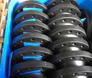
ASTM A350 LF2 Reducing Flanges
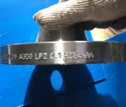
A350 Gr. LF2 CL.1 Weld Neck Flanges
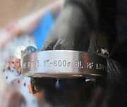
SA350 LF2 Blind Flanges
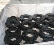
Carbon Steel A350 Flat Face Flanges
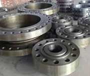
Low Temperature Steel A350 LF2 RTJ Flanges
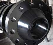
LTCS A350 Raised Face Flanges
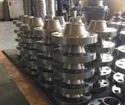
A350 LF2 Carbon Steel Socket Weld Flanges
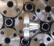
350 LF2 Slip On Flanges
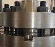
ASTM A350 LF2 Orifice Flanges
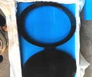
CS A350 Lf2 Forgings Spectacle Flanges
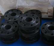
A350-Lf2-1 Forged Flanges
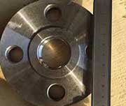
A350 Class 1 Screwed Flanges
| TEMP °C |
Carbon Class 150 | Carbon Class 300 | Carbon Class 400 | Carbon Class 600 | Carbon Class 900 | Carbon Class 1500 | Carbon Class 2500 |
| -29 TO 38 | 19.6 | 51.1 | 68.1 | 102.1 | 153.2 | 255.3 | 425.5 |
| 50 | 19.2 | 50.1 | 66.8 | 100.2 | 150.4 | 250.6 | 417.7 |
| 100 | 17.7 | 46.6 | 62.1 | 93.2 | 139.8 | 233 | 388.3 |
| 150 | 15.8 | 45.1 | 60.1 | 90.2 | 135.2 | 225.4 | 375.6 |
| 200 | 13.8 | 43.8 | 58.4 | 87.6 | 131.4 | 219 | 365 |
| 250 | 12.1 | 41.9 | 55.9 | 83.9 | 125.8 | 209.7 | 349.5 |
| 300 | 10.2 | 39.8 | 53.1 | 79.6 | 119.5 | 199.1 | 331.8 |
| 325 | 9.3 | 38.7 | 51.6 | 77.4 | 116.1 | 193.6 | 322.6 |
| 350 | 8.4 | 37.6 | 50.1 | 75.1 | 112.7 | 187.8 | 313 |
| 375 | 7.4 | 36.4 | 48.5 | 72.7 | 109.1 | 181.8 | 303.1 |
| 400 | 6.5 | 34.7 | 46.3 | 69.4 | 104.2 | 173.6 | 289.3 |
| 425 | 5.5 | 28.8 | 38.4 | 57.5 | 86.3 | 143.8 | 239.7 |
| 450 | 4.6 | 23 | 30.7 | 46 | 69 | 115 | 191.7 |
| 475 | 3.7 | 17.4 | 23.2 | 34.9 | 52.3 | 87.2 | 145.3 |
| 500 | 2.8 | 11.8 | 15.7 | 23.5 | 35.3 | 58.8 | 97.9 |
| 538 | 1.4 | 5.9 | 7.9 | 11.8 | 17.7 | 29.5 | 49.2 |
| TEMP °C |
150 | 300 | 400 | 600 | 900 | 1500 | 2500 |
| LF1 and LF5 Class 1 | LF2 Classes 1 and 2 | LF3 Classes 1 and LF 5 Class 2 | LF 6 | LF 9 | LF 787 | |||
|---|---|---|---|---|---|---|---|---|
| Class 1 | Class | Class 2 | Class 3 | |||||
| Tensile strength, ksi [MPa] | 60-85 [415- 585] | 70-95 [485- 655] | 70-95 [485- 655] | 66-91 [455-630] | 75-100 [515-690] | 63-88 [435- 605] | 65-85 [450-585] | 75-95 [515-655] |
| Yield strength, minimum, ksi [MPa]B,C Elongation: | 30 [205] | 36 [250] | 37.5 [260] | 52 [360] | 60 [415] | 46 [315] | 55 [380] | 65 [450] |
| Standard round specimen, or small proportional specimen, minimum % in | 25 | 22 | 22 | 22 | 20 | 25 | 20 | 20 |
| 4D gage length Strip specimen to wall thickness 5⁄16 in. (7.94 millimeter) and over and for all small sizes tested in full section; min % in 2 in. (50 millimeter) | 28 | 30 | 30 | 30 | 28 | 28 | 28 | 28 |
| Equation for calculating min elongation for strip specimens thinner than 5⁄16 in. (7.94 millimeter); min % in 2 in. (50 millimeter) t p actual thickness in inches | 48t+13 | 48t+15 | 48t+15 | 48t+15 | 48t+13 | 48t+13 | 48t+13 | 48t+13 |
| Reduction of area, min, % | 38 | 30 | 35 | 40 | 40 | 38 | 45 | 45 |
| Properties | Metric | Imperial |
|---|---|---|
| Thermal expansion co-efficient (@0-100°C/32-212°F) | 10.4 µm/m°C | 5.78 µin/in°F |
| Thermal conductivity | 21.6 W/mK | 150 BTU in/hr.ft².°F |
| Chemical Properties | Mechanical Properties | |
|---|---|---|
| C 0.30 Max | TS Min psi (Mpa) | 70,000 (485) |
| Mn 0.60 – 1.35 | YS Min psi (Mpa) | 36,000 (250) |
| Si 0.15 – 0.30 | EL (2″ Min) | 22% |
| P 0.035 Max | RA Min | 30% |
| S 0.040 Max | Hardness, Bhn | Max 197 |
| Cr 0.30 Max | -50ºF Charpy | Min Impact |
| Ni 0.40 Max | Energy F t/Lb (J):- | |
| Mo 0.12 Max | Set of 3 Specimen* | 15 (20) |
| V 0.08 Max | For One Specimen | 12 (16) |
| Cb 0.02 Max | ||
| Cu 0.04 Max | ||
| Pb 0.02 Max | ||
| Total Residuals = 0.50 | ||
| Physical Properties | Cast Carbon Steel | Forged |
|---|---|---|
| 0.30/0.35 C Max | A216-WCB | A105 |
| 0.25 C Max | A216-WCC | |
| Low Temperature Steel | ||
| 0.25/0.30 C Max | A352-LCB | A350-LF2 |
| 0.5 Mo | A352-LC1 | |
| 2.5 Ni | A352-LC2 | |
| 3.5 Ni | A352-LC3 | |
| C-MN-Si (0.25 Max) | A352-LCC | A350-LF3 |
| C-MN-Si-V (1.15~1.50 Mn) | A350-LF6 | |