-
-
send us mail
[email protected]
These carbon steel ASTM A105 Flanges have improved mechanical properties because forging refines and directs the flow of grain according to the shape of the piece, which in this case is the flange. Forging reduces the weight required to manufacture the ASTM A105n Weld Neck Flanges, therefore, thereby providing significant cost savings. Also, since the flanges have less excess, the CS SORF Flanges A105 would require less machining hours along with much less material which could be used to clean the piece at the end.
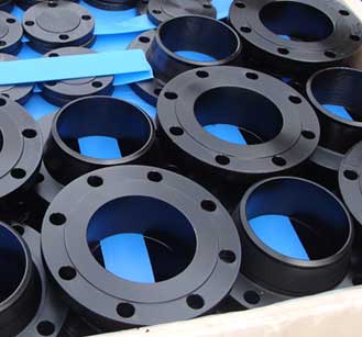
ASTM A105 Flanges
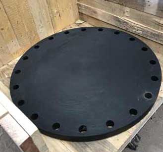
SA105 Pipe Flanges
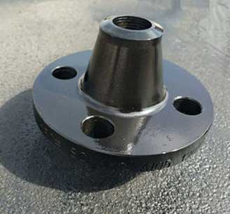
CS SORF Flanges A105
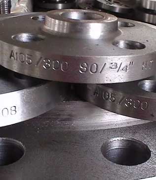
Forged carbon steel components such as flanges produced in accordance with ASTM A105 are designed for use at both ambient as well as elevated temperature settings.
In order to improve its performance at elevated temperatures, the Carbon Steel ASTM A105 Blind Flanges are often heat treated by the performance of procedures such as annealing, normalizing, tempering, or quenching. After undergoing forging operations, the ASTM A105 Carbon Steel Flanges is to be subjected to tension test, hardness test and hydrostatic test, with the latter being applicable when required. Recommendations for retreatment, repair by welding, and product marking for the Carbon Steel SA105 Pipe Flanges are given in the specification.
| Specification : | ASTM A105 Flanges |
| Size Chart : | 1/2″ (15 NB) To 48″ (1200NB) |
| Production Process: | Machined, Forged, Heat Treated |
| Coating Flange Faces : | Anti-rust Paint, Cold and Hot Dip Galvanized, Zinc Plated, Yellow Transparent, Oil Black Paint |
| Common Types of Flange : | Flange 150 LB WNRF Class 300 RTJ 600# BLRF Class 900 SORF |
| Design For Size: | DIN ASTM A105 Flanges, JIS ASTM A105 Flanges, ANSI ASTM A105 Flanges, BS ASTM A105 Flanges, PN ASTM A105 Flanges, EN ASTM A105 Flanges, ASA ASTM A105 Flanges, ASME ASTM A105 Flanges |
| Flange Machining Equipment: | Sand-blasting machine, Press machine, Bending machine, Pushing Machine, electric bevelling machine etc |
| Standards: | ASME B16.38 ASTM A105 Flanges, EN-1092 ASTM A105 Flanges, BS10 ASTM A105 Flanges, DIN ASTM A105 Flanges, PN ASTM A105 Flanges, JIS ASTM A105 Flanges, ISO ASTM A105 Flanges, GOST ASTM A105 Flanges, UNI ASTM A105 Flanges, AWWA ASTM A105 Flanges, MSS SP44 ASTM A105 Flanges, ASME B16.5 ASTM A105 Flanges, ASME B16.47 (Series A, Series B) ASTM A105 Flanges |
| Pressure Rating Table: | Class 150 LBS, Class 300 LBS, Class 600 LBS, Class 900 LBS, Class 1500 LBS, Class 2500 LBS |
| Connect Type: | LMF, SMF, RF, FF, RTJ, LJF |
| Supporting Flange Material: | Flange Bolts, Gasket, Ring Joint |
| Application: | Nuclear Power Plant Natural Gas Industry Chemical Industry Fabrication Industry Oil And Gas Industry Water Pipeline Industry |
| ASTM A105 Flange Weights by Pressure Class and Size | ||||||||||||||||||
| Pipe Size | Class 150 | Class 300 | Class 600 | Class 900 | Class 1500 | Class 2500 | ||||||||||||
| WN | SO | BLD | WN | SO | BLD | WN | SO | BLD | WN | SO | BLD | WN | SO | BLD | WN | SO | BLD | |
| 1/2" | 2 | 1 | 1 | 2 | 1 | 1 | 2 | 2 | 2 | 1500 Class Weight | 5 | 4 | 4 | 7 | 7 | 7 | ||
| 3/4" | 2 | 2 | 2 | 3 | 3 | 3 | 4 | 3 | 3 | 1500 Class Weight | 6 | 5 | 6 | 8 | 8 | 8 | ||
| 1" | 3 | 2 | 2 | 4 | 3 | 3 | 4 | 4 | 4 | 1500 Class Weight | 9 | 8 | 8 | 12 | 11 | 11 | ||
| 1 1/2" | 4 | 3 | 3 | 7 | 6 | 6 | 8 | 7 | 8 | 1500 Class Weight | 13 | 12 | 13 | 25 | 22 | 23 | ||
| 2" | 6 | 5 | 5 | 9 | 7 | 8 | 12 | 9 | 10 | 1500 Class Weight | 25 | 25 | 25 | 42 | 37 | 39 | ||
| 2 1/2" | 8 | 7 | 7 | 12 | 10 | 12 | 18 | 13 | 15 | 1500 Class Weight | 36 | 36 | 35 | 52 | 55 | 56 | ||
| 3" | 10 | 8 | 9 | 15 | 13 | 16 | 23 | 16 | 20 | 31 | 26 | 29 | 48 | 48 | 48 | 94 | 83 | 86 |
| 4" | 15 | 13 | 17 | 25 | 22 | 27 | 42 | 37 | 41 | 53 | 53 | 54 | 73 | 73 | 73 | 145 | 125 | 130 |
| 5" | 19 | 15 | 20 | 32 | 28 | 35 | 68 | 63 | 68 | 86 | 83 | 87 | 130 | 130 | 140 | 245 | 210 | 225 |
| 6" | 24 | 19 | 26 | 42 | 39 | 50 | 81 | 80 | 86 | 110 | 110 | 115 | 165 | 165 | 160 | 380 | 325 | 345 |
| 8" | 39 | 30 | 45 | 67 | 58 | 81 | 120 | 115 | 140 | 175 | 170 | 200 | 275 | 260 | 300 | 580 | 485 | 530 |
| 10" | 52 | 43 | 70 | 91 | 81 | 124 | 190 | 170 | 230 | 260 | 245 | 290 | 455 | 435 | 510 | 1075 | 930 | 1025 |
| 12" | 80 | 64 | 110 | 140 | 115 | 185 | 225 | 200 | 295 | 325 | 325 | 415 | 690 | 580 | 690 | 1525 | 1100 | 1300 |
| 14" | 110 | 90 | 140 | 180 | 165 | 250 | 280 | 230 | 355 | 400 | 400 | 520 | 940 | NA | 975 | NA | NA | NA |
| 16" | 140 | 98 | 180 | 250 | 190 | 295 | 390 | 330 | 495 | 495 | 425 | 600 | 1250 | NA | 1300 | NA | NA | NA |
| 18" | 150 | 130 | 220 | 320 | 250 | 395 | 475 | 400 | 630 | 680 | 600 | 850 | 1625 | NA | 1750 | NA | NA | NA |
| 20" | 180 | 165 | 285 | 400 | 315 | 505 | 590 | 510 | 810 | 830 | 730 | 1075 | 2050 | NA | 2225 | NA | NA | NA |
| 22" | 225 | 185 | 355 | 465 | 370 | 640 | 720 | 590 | 1000 | NA | NA | NA | NA | NA | NA | NA | NA | NA |
| 24" | 260 | 220 | 430 | 580 | 475 | 790 | 830 | 730 | 1250 | 1500 | 1400 | 2025 | 3325 | NA | 3625 | NA | NA | NA |
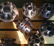
ASTM A105 Class 150 Orifice Flanges
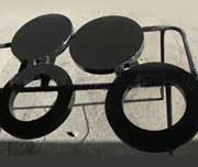
ASME B16.5 A105 Spectacle Flanges
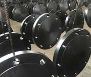
ASTM A105 Carbon Steel Forged Flanges
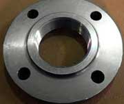
Carbon Steel ASTM A105 Screwed Flanges
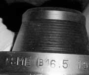
Carbon Steel SA105 Reducing Flanges
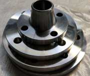
CS ASTM A105 Weld Neck Flanges
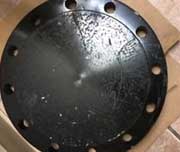
ASTM A105 Carbon Steel Blind Flanges
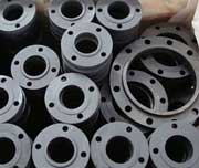
Carbon Steel ASTM A105 Flat Face Flanges
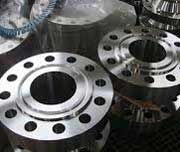
CS ASTM A105 RTJ Flanges
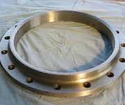
ASTM A105 Raised Face Flanges
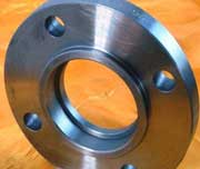
ANSI A105 Socket Weld Flanges
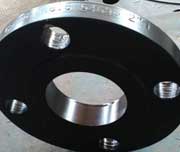
SA 105 Slip On Flanges
| Elements | Composition, % |
| Carbon [C] | ≤0.35 |
| Manganese [Mn] | 0.60-1.05 |
| Phosphorus [P] | ≤0.35 |
| Sulfur [S] | ≤0.40 |
| Silicon [Si] | 0.10-0.35 |
| Copper [Cu] | ≤0.40 |
| Nickel [Ni] | ≤0.40 |
| Chromium [Cr] | ≤0.30 |
| Molybdenum [Mo] | ≤0.12 |
| Vanadium [V] | ≤0.08 |
| Tensile Strength min. | Yield Strength min. | Elongation min. | Reduction of Area, min. | Hardness | ||
|---|---|---|---|---|---|---|
| MPa | ksi | MPa | ksi | % | % | HBW |
| 485 | 70 | 250 | 36 | 22 | 30 | 137-187 |
| Density (lb / cu. in.) | 0.284 |
| Specific Gravity | 7.9 |
| Specific Heat (Btu/lb/Deg F - [32-212 Deg F]) | 0.107 |
| Melting Point (Deg F) | 2740 |
| Thermal Conductivity | 360 |
| Mean Coeff Thermal Expansion | 6.7 |
| Modulus of Elasticity Tension | 30 |
| Modulus of Elasticity Torsion | 11 |
Grade |
Yield Strength (0.2% offset),minimum, ksi [MPa] |
Tensile Strength, min, ksi [MPa] |
Elongation in 2 in, or 50 mm, minimeter % |
|---|---|---|---|
F42 |
42 [290] |
60 [415] |
20 |
F46 |
46 [315] |
60 [415] |
20 |
F48 |
48 [330] |
62 [420] |
20 |
F50 |
50 [345] |
64 [440] |
20 |
F52 |
52 [360] |
66 [455] |
20 |
F56 |
56 [385] |
68 [470] |
20 |
F60 |
60 [415] |
75 [515] |
20 |
F65 |
65 [450] |
77 [530] |
20 |
F70 |
70 [485] |
82 [565] |
18 |
| Size in In. | Size in millimeter | Outer Diameter | Flange Thick. | RF Diameter | RF Height | PCD | No of Bolts | Bolt Size UNC | Machine Bolt Length | RF Stud Length | Hole Size | ISO Stud Size | Weight in kilogram |
| A | B | C | D | E | |||||||||
| 1/2 | 15 | 90 | 9.6 | 34.9 | 2 | 60.3 | 4 | 1/2 | 50 | 55 | 5/8 | M14 | 0.9 |
| 3/4 | 20 | 100 | 11.2 | 42.9 | 2 | 69.9 | 4 | 1/2 | 50 | 65 | 5/8 | M14 | 0.9 |
| 1 | 25 | 110 | 12.7 | 50.8 | 2 | 79.4 | 4 | 1/2 | 55 | 65 | 5/8 | M14 | 0.9 |
| 1 1/4 | 32 | 115 | 14.3 | 63.5 | 2 | 88.9 | 4 | 1/2 | 55 | 70 | 5/8 | M14 | 1.4 |
| 1 1/2 | 40 | 125 | 15.9 | 73 | 2 | 98.4 | 4 | 1/2 | 65 | 70 | 5/8 | M14 | 1.8 |
| 2 | 50 | 150 | 17.5 | 92.1 | 2 | 120.7 | 4 | 5/8 | 70 | 85 | 3/4 | M16 | 2.3 |
| 2 1/2 | 65 | 180 | 20.7 | 104.8 | 2 | 139.7 | 4 | 5/8 | 75 | 90 | 3/4 | M16 | 3.2 |
| 3 | 80 | 190 | 22.3 | 127 | 2 | 152.4 | 4 | 5/8 | 75 | 90 | 3/4 | M16 | 4.1 |
| 3 1/2 | 90 | 215 | 22.3 | 139.7 | 2 | 177.8 | 8 | 5/8 | 75 | 90 | 3/4 | M16 | 5.9 |
| 4 | 100 | 230 | 22.3 | 157.2 | 2 | 190.5 | 8 | 5/8 | 75 | 90 | 3/4 | M16 | 7.7 |
| 5 | 125 | 255 | 22.3 | 185.7 | 2 | 215.9 | 8 | 3/4 | 85 | 95 | 7/8 | M20 | 9.1 |
| 6 | 150 | 280 | 23.9 | 215.9 | 2 | 241.3 | 8 | 3/4 | 85 | 100 | 7/8 | M20 | 11.8 |
| 8 | 200 | 345 | 27 | 269.9 | 2 | 298.5 | 8 | 3/4 | 90 | 110 | 7/8 | M20 | 20.5 |
| 10 | 250 | 405 | 28.6 | 323.8 | 2 | 362 | 12 | 7/8 | 100 | 115 | 1 | M24 | 32 |
| 12 | 300 | 485 | 30.2 | 381 | 2 | 431.8 | 12 | 7/8 | 100 | 120 | 1 | M24 | 50 |
| 14 | 350 | 535 | 33.4 | 412.8 | 2 | 476.3 | 12 | 1 | 115 | 135 | 1 1/8 | M27 | 64 |
| 16 | 400 | 595 | 35 | 469.9 | 2 | 539.8 | 16 | 1 | 115 | 135 | 1 1/8 | M27 | 82 |
| 18 | 450 | 635 | 38.1 | 533.4 | 2 | 577.9 | 16 | 1 1/8 | 125 | 145 | 1 1/4 | M30 | 100 |
| 20 | 500 | 700 | 41.3 | 584.2 | 2 | 635 | 20 | 1 1/8 | 140 | 160 | 1 1/4 | M30 | 130 |
| 24 | 600 | 815 | 46.1 | 692.2 | 2 | 749.3 | 20 | 1 1/4 | 150 | 170 | 1 3/8 | M33 | 196 |