-
-
send us mail
[email protected]
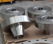
Welding Neck Flanges are probably the most easiest to recognize amongst the various types of flanges available in the market. The ASME B16.5 Weld Neck Flange is produced with a long tapered hub, which transitions gradually over to the wall thickness from a pipe or fitting.
The long tapered hub present on the ASME B16.5 Carbon Steel Weld Neck Flange is what provides an important reinforcement to this component. This reinforcement provided by the flanges is useful in several applications involving high pressure as well as sub-zero and / or elevated temperatures. Therefore Alloy Steel 150 Welding Neck Flange is used across a wide range of industries. The smooth transition from flanges thickness to pipe wall thickness or fitting wall thickness effected by the taper is extremely beneficial, especially under conditions, where repeated bending may occur. The bending could be caused by either line expansion or other variable forces.
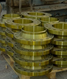
Buy Weld Neck Flange, 4 inch, 300 LBS, Schedule 40 * Schedule 80, ASTM A105, ASME B16.5 At Factory Price.
The Stainless Steel Weld Neck Flange is bored to match the inside diameter of the mating pipe or fitting. Since the bores of both flanges and pipe match, there will be an unrestricted flow of product. This, in turn, is what prevents turbulence at the joint, while also reducing erosion. The flange also provides excellent stress distribution through the tapered hub. Moreover, these flanges are easily radiographed for flaw detection. The ASME B16.5 - 1996 Pipe Flanges and Flange Fittings standard envelopes pressure-temperature ratings, materials, ANSI B16.5 WNRF Flange Dimensions, tolerances, marking, testing, as well as methods of designating openings for pipe flanges and flanged fittings.
The standard includes flanges with 4 inch Weld Neck Pipe Flanges Pressure Rating class designations 150, 300, 400, 600, 900, 1500 and 2500.
| Specification : | ASME B16.5 Weld Neck Flange |
| Connect Type Type: | RF, FF, RTJ, LMF, SMF, LJF. |
| ASA Flange Size Chart : | 1/2″ (15 NB) To 48″ (1200NB) |
| Flange Standards : | ASME B16.5, ASME B16.47 (Series A, Series B), ASME B16.38, EN-1092, BS10, DIN, PN, JIS, ISO, GOST, UNI, AWWA, MSS SP44. |
| Flange Machining Equipment: | Bending machine, Pushing Machine, Sand-blasting machine, Press machine, electric bevelling machine etc |
| Flange Production Process: | Forged, Heat Treated and Machined |
| Design For Size: | ASA, ASME, DIN, PN, JIS, ANSI, BS, EN |
| ASME B16.5 Flange Application: | Oil And Gas Industry Chemical Industry Natural Gas Industry Water Pipeline Industry Fabrication Industry Nuclear Power Plant |
| Flange Pressure Rating Table: | Class 150 LBS, Class 300 LBS, Class 600 LBS, Class 900 LBS, Class 1500 LBS, Class 2500 LBS |
| Coating Flange Faces : | Yellow Transparent, Oil Black Paint, Anti-rust Paint, Cold and Hot Dip Galvanized, Zinc Plated |
| Welding Neck Flange Bores (in inch) | ||||||||||||||
| NPS | O D |
Sch 10 |
Sch 20 |
Sch 30 |
Std. Wall |
Sch 40 |
Sch 60 |
Extra Strong |
Sch 80 |
Sch 100 |
Sch 120 |
Sch 140 |
Sch 160 |
Double Extra Strong |
| 1/2” | 0.840 | 0.674 | 0.622 | 0.622 | 0.546 | 0.546 | 0.464 | 0.252 | ||||||
| 3/4” | 1.050 | 0.884 | 0.824 | 0.824 | 0.742 | 0.742 | 0.612 | 0.434 | ||||||
| 1” | 1.315 | 1.097 | 1.049 | 1.049 | 0.957 | 0.957 | 0.815 | 0.599 | ||||||
| 1.1/4” | 1.660 | 1.442 | 1.380 | 1.380 | 1.278 | 1.278 | 1.160 | 0.896 | ||||||
| 1.1/2” | 1.900 | 1.682 | 1.610 | 1.610 | 1.500 | 1.500 | 1.338 | 1.100 | ||||||
| 2” | 2.375 | 2.157 | 2.067 | 2.067 | 1.939 | 1.939 | 1.687 | 1.503 | ||||||
| 2.1/2” | 2.875 | 2.635 | 2.469 | 2.469 | 2.323 | 2.323 | 2.125 | 1.771 | ||||||
| 3” | 3.500 | 3.260 | 3.068 | 3.068 | 2.900 | 2.900 | 2.624 | 2.300 | ||||||
| 3-1/2” | 4.000 | 3.760 | 3.548 | 3.548 | 3.364 | 3.364 | 2.728 | |||||||
| 4” | 4.500 | 4.260 | 4.026 | 4.026 | 3.826 | 3.826 | 3.624 | 3.438 | 3.152 | |||||
| 5” | 5.563 | 5.295 | 5.047 | 5.047 | 4.813 | 4.813 | 4.563 | 4.313 | 4.063 | |||||
| 6” | 6.625 | 6.357 | 6.065 | 6.065 | 5.761 | 5.761 | 5.501 | 5.187 | 4.897 | |||||
| 8” | 8.625 | 8.329 | 8.125 | 8.071 | 7.981 | 7.981 | 7.813 | 7.625 | 7.625 | 7.437 | 7.187 | 7.001 | 6.813 | 6.875 |
| 10” | 10.750 | 10.420 | 10.250 | 10.136 | 10.020 | 10.020 | 9.750 | 9.750 | 9.562 | 9.312 | 9.062 | 8.750 | 8.500 | 8.750 |
| 12” | 12.750 | 12.390 | 12.250 | 12.090 | 12.000 | 11.938 | 11.626 | 11.750 | 11.374 | 11.062 | 10.750 | 10.500 | 10.126 | 10.750 |
| 14” | 14.000 | 13.500 | 13.376 | 13.250 | 13.250 | 13.124 | 12.812 | 13.000 | 12.500 | 12.124 | 11.814 | 11.500 | 11.188 | |
| 16” | 16.000 | 15.500 | 15.376 | 15.250 | 15.250 | 15.000 | 14.688 | 15.000 | 14.312 | 13.938 | 13.564 | 13.124 | 12.812 | |
| 18” | 18.000 | 17.500 | 17.376 | 17.124 | 17.250 | 16.876 | 16.500 | 17.000 | 16.124 | 15.688 | 15.250 | 14.876 | 14.438 | |
| 20” | 20.000 | 19.500 | 19.250 | 19.000 | 19.250 | 18.812 | 18.376 | 19.000 | 17.938 | 17.438 | 17.000 | 16.500 | 16.062 | |
| 24” | 24.000 | 23.500 | 23.250 | 22.876 | 23.250 | 22.624 | 22.062 | 23.000 | 21.562 | 20.938 | 20.376 | 19.876 | 19.312 | |
| 30” | 30.000 | 29.376 | 29.000 | 28.750 | 29.250 | 29.000 | ||||||||
| 36” | 36.000 | 35.376 | 35.000 | 34.750 | 35.250 | 34.500 | 35.000 | |||||||
| 42” | 42.000 | 41.250 | 41.000 | |||||||||||
| ANSI B16.5 Sch 40 Weld Neck Flanges Pressure Ratings | ||||||||||||||||||
| NPS | 150LBS | 300LBS | 600LBS | 900LBS | 1500LBS | 2500LBS | ||||||||||||
| WN | S/O | B/K | WN | S/O | B/K | WN | S/O | B/K | WN | S/O | B/K | WN | S/O | B/K | WN | S/O | B/K | |
| 1/2” | 0.7 | 0.4 | 0.5 | 0.8 | 0.7 | 0.8 | 0.9 | 0.8 | 0.8 | 2.1 | 1.8 | 1.9 | 2.1 | 1.8 | 1.9 | 3.2 | 3 | 3 |
| 3/4” | 0.8 | 0.7 | 0.8 | 1.4 | 1.2 | 1.2 | 1.6 | 1.4 | 1.4 | 2.7 | 2.4 | 2.7 | 2.7 | 2.4 | 2.7 | 3.6 | 4 | 4.5 |
| 1” | 1.1 | 0.8 | 0.9 | 1.7 | 1.4 | 1.5 | 1.9 | 1.7 | 1.7 | 3.9 | 3.6 | 3.7 | 3.9 | 3.6 | 3.7 | 5.4 | 5 | 5 |
| 1.1/4” | 1.5 | 1.2 | 1.3 | 2.2 | 1.8 | 2 | 2.6 | 2.1 | 2.4 | 4.5 | 4.1 | 4.3 | 4.5 | 4.1 | 4.3 | 7.8 | 8 | 8 |
| 1.1/2” | 1.8 | 1.4 | 1.6 | 3.2 | 2.7 | 2.9 | 3.6 | 3.1 | 3.4 | 6.2 | 5.4 | 5.9 | 6.2 | 5.4 | 5.9 | 11.5 | 11 | 11 |
| 2” | 2.7 | 2.2 | 2.6 | 3.6 | 3.2 | 3.5 | 4.7 | 3.9 | 4.4 | 11.3 | 10.5 | 11.3 | 11.3 | 10.5 | 11.3 | 19 | 17 | 17 |
| 2.1/2” | 4.4 | 3.5 | 4.1 | 5.4 | 4.5 | 5.3 | 4.8 | 5.4 | 6.8 | 16.3 | 15.8 | 16 | 16.3 | 15.8 | 16 | 24 | 25 | 25 |
| 3” | 5.2 | 3.8 | 5.1 | 7.3 | 5.9 | 7.2 | 8.7 | 7.3 | 8.9 | 15 | 12.3 | 16.8 | 21 | 21.5 | 19.5 | 42.6 | 38 | 39 |
| 3-1/2” | 6.4 | 5 | 6.5 | 8.9 | 7.5 | 9.2 | 11.6 | 9 | 12.7 | – | – | – | – | – | – | – | – | – |
| 4” | 7.5 | 5.6 | 7.5 | 11.8 | 10 | 12.2 | 18.4 | 16.5 | 18.6 | 24 | 23.2 | 24.5 | 31.8 | 31 | 33 | 64 | 58 | 60 |
| 5” | 9.2 | 6.5 | 9.2 | 16 | 12.5 | 16 | 31 | 28.5 | 30.8 | 38.5 | 37.5 | 39.5 | 59 | 58.8 | 60 | 111 | 95 | 101 |
| 6” | 11.0 | 8.1 | 11.8 | 20.2 | 16.5 | 22 | 37 | 36.2 | 38 | 50 | 48.3 | 51.5 | 72 | 74 | 75 | 171 | 146 | 156 |
| 8” | 18.4 | 13 | 20.4 | 31.2 | 25.5 | 36 | 54.5 | 51.5 | 62.2 | 85 | 75 | 89 | 124 | 112 | 125 | 261 | 220 | 242 |
| 10” | 25.5 | 18.4 | 31 | 44.3 | 35 | 55 | 98.5 | 76.2 | 102 | 123 | 110 | 131 | 207 | 184 | 215 | 485 | 420 | 465 |
| 12” | 37 | 28.5 | 47 | 63.5 | 52 | 82.5 | 105 | 89.5 | 132 | 168 | 146 | 187 | 306 | 264 | 316 | 698 | 590 | 665 |
| 14” | 51 | 37.5 | 60 | 86 | 73 | 108 | 150 | 102 | 158 | 198 | 172 | 224 | 416 | – | – | – | – | – |
| 16” | 61.5 | 44.5 | 61 | 112 | 88 | 139 | 177 | 150 | 225 | 225 | 192 | 259 | 567 | – | – | – | – | – |
| 18” | 71.5 | 54 | 93 | 141 | 115 | 178 | 228 | 180 | 285 | 318 | 272 | 383 | 736 | – | – | – | – | – |
| 20” | 85 | 72 | 127 | 173 | 139 | 228 | 285 | 231 | 365 | 376 | 330 | 482 | 929 | – | – | – | – | – |
| 24” | 119 | 95 | 190 | 248 | 212 | 350 | 372 | 330 | 532 | 680 | 632 | 905 | 1504 | – | – | – | – | – |
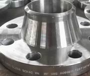
Stainless steel ANSI B16.5 F316 Welding Neck Flange
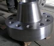
ANSI b16.5 Forged Class 150 Weld Neck Pipe Flange
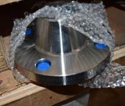
ASME B16.5 150LBS Raised Face Weld Neck Flange
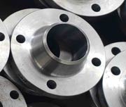
PN10 Standard SCH 40 Reducing Weld Neck Flange
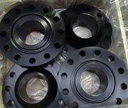
2 Inch BS4504 Flat Face Weld Neck Flange
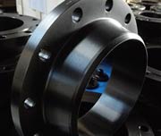
1/2 To 2/4 Inch Stainless Steel Weld Neck Flange
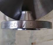
DIN Standard PN25 Rtj Weld Neck Flange
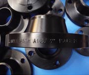
Forged DN100 Class 300 RF Welding Neck Flange Din En 1092 1
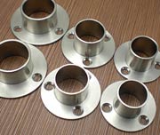
SS 400 Forged or Casting Welding Neck Flange 300 Lbs
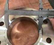
ASME SA-182 Jis 16k Weld Neck Flange
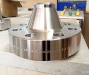
BS10 Table E Weld Neck Flange
GOST 12820-80 304 / 304L 5 WNRF Flange Class 150
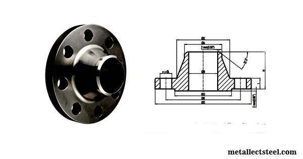
| Size in In. | Size in Millimeter | Outer Diameter (OD) | Flange Thick. | Hub OD | Weld Neck OD | Welding Neck Length | Bore | RF Diameter | RF Height | PCD | Weld Face |
| A | B | C | D | E | F | G | H | I | J | ||
| 1/2 | 15 | 90 | 9.6 | 30 | 21.3 | 46 | Refer Note | 34.9 | 2 | 60.3 | 1.6 |
| 3/4 | 20 | 100 | 11.2 | 38 | 26.7 | 51 | 42.9 | 2 | 69.9 | 1.6 | |
| 1 | 25 | 110 | 12.7 | 49 | 33.4 | 54 | 50.8 | 2 | 79.4 | 1.6 | |
| 1 1/4 | 32 | 115 | 14.3 | 59 | 42.2 | 56 | 63.5 | 2 | 88.9 | 1.6 | |
| 1 1/2 | 40 | 125 | 15.9 | 65 | 48.3 | 60 | 73 | 2 | 98.4 | 1.6 | |
| 2 | 50 | 150 | 17.5 | 78 | 60.3 | 62 | 92.1 | 2 | 120.7 | 1.6 | |
| 2 1/2 | 65 | 180 | 20.7 | 90 | 73 | 68 | 104.8 | 2 | 139.7 | 1.6 | |
| 3 | 80 | 190 | 22.3 | 108 | 88.9 | 68 | 127 | 2 | 152.4 | 1.6 | |
| 3 1/2 | 90 | 215 | 22.3 | 122 | 101.6 | 70 | 139.7 | 2 | 177.8 | 1.6 | |
| 4 | 100 | 230 | 22.3 | 135 | 114.3 | 75 | 157.2 | 2 | 190.5 | 1.6 | |
| 5 | 125 | 255 | 22.3 | 164 | 141.3 | 87 | 185.7 | 2 | 215.9 | 1.6 | |
| 6 | 150 | 280 | 23.9 | 192 | 168.3 | 87 | 215.9 | 2 | 241.3 | 1.6 | |
| 8 | 200 | 345 | 27 | 246 | 219.1 | 100 | 269.9 | 2 | 298.5 | 1.6 | |
| 10 | 250 | 405 | 28.6 | 305 | 273 | 100 | 323.8 | 2 | 362 | 1.6 | |
| 12 | 300 | 485 | 30.2 | 365 | 323.8 | 113 | 381 | 2 | 431.8 | 1.6 | |
| 14 | 350 | 535 | 33.4 | 400 | 355.6 | 125 | 412.8 | 2 | 476.3 | 1.6 | |
| 16 | 400 | 595 | 35 | 457 | 406.4 | 125 | 469.9 | 2 | 539.8 | 1.6 | |
| 18 | 450 | 635 | 38.1 | 505 | 457.2 | 138 | 533.4 | 2 | 577.9 | 1.6 | |
| 20 | 500 | 700 | 41.3 | 559 | 508 | 143 | 584.2 | 2 | 635 | 1.6 | |
| 24 | 600 | 815 | 46.1 | 663 | 610 | 151 | 692.2 | 2 | 749.3 | 1.6 |
| Size in In | Size in Millimeter | (OD) Outer Diameter | Flange Thick. | Hub OD | Weld Neck Outer Diameter | Welding Neck Length | Bore | RF Diameter | RF Height | PCD | Weld Face |
| A | B | C | D | E | F | G | H | I | J | ||
| 1/2 | 15 | 95 | 12.7 | 38 | 21.3 | 51 | Refer Note | 34.9 | 2 | 66.7 | 1.6 |
| 3/4 | 20 | 115 | 14.3 | 48 | 26.7 | 56 | 42.9 | 2 | 82.6 | 1.6 | |
| 1 | 25 | 125 | 15.9 | 54 | 33.4 | 60 | 50.8 | 2 | 88.9 | 1.6 | |
| 1 1/4 | 32 | 135 | 17.5 | 64 | 42.2 | 64 | 63.5 | 2 | 98.4 | 1.6 | |
| 1 1/2 | 40 | 155 | 19.1 | 70 | 48.3 | 67 | 73 | 2 | 114.3 | 1.6 | |
| 2 | 50 | 165 | 20.7 | 84 | 60.3 | 68 | 92.1 | 2 | 127 | 1.6 | |
| 2 1/2 | 65 | 190 | 23.9 | 100 | 73 | 75 | 104.8 | 2 | 149.2 | 1.6 | |
| 3 | 80 | 210 | 27 | 117 | 88.9 | 78 | 127 | 2 | 168.3 | 1.6 | |
| 3 1/2 | 90 | 230 | 28.6 | 133 | 101.6 | 79 | 139.7 | 2 | 184.2 | 1.6 | |
| 4 | 100 | 255 | 30.2 | 146 | 114.3 | 84 | 157.2 | 2 | 200 | 1.6 | |
| 5 | 125 | 280 | 33.4 | 178 | 141.3 | 97 | 185.7 | 2 | 235 | 1.6 | |
| 6 | 150 | 320 | 35 | 206 | 168.3 | 97 | 215.9 | 2 | 269.9 | 1.6 | |
| 8 | 200 | 380 | 39.7 | 260 | 219.1 | 110 | 269.9 | 2 | 330.2 | 1.6 | |
| 10 | 250 | 445 | 46.1 | 321 | 273 | 116 | 323.8 | 2 | 387.4 | 1.6 | |
| 12 | 300 | 520 | 49.3 | 375 | 323.8 | 129 | 381 | 2 | 450.8 | 1.6 | |
| 14 | 350 | 585 | 52.4 | 425 | 355.6 | 141 | 412.8 | 2 | 514.4 | 1.6 | |
| 16 | 400 | 650 | 55.6 | 483 | 406.4 | 144 | 469.9 | 2 | 571.5 | 1.6 | |
| 18 | 450 | 710 | 58.8 | 533 | 457 | 157 | 533.4 | 2 | 628.6 | 1.6 | |
| 20 | 500 | 775 | 62 | 587 | 508 | 160 | 584.2 | 2 | 685.8 | 1.6 | |
| 24 | 600 | 915 | 68.3 | 702 | 610 | 167 | 692.2 | 2 | 812.8 | 1.6 |
| Size in In. | Size in Millimeter | (OD) Outer Diameter | Flange Thick. | Hub Outer Diameter | Weld Neck Outer Diameter | Welding Neck Length | Bore | RF Diameter | RF Height | PCD | Weld Face |
| A | B | C | D | E | F | G | H | I | J | ||
| 1/2 | 15 | 95 | 14.3 | 38 | 21.3 | 52 | Refer Note | 34.9 | 7 | 66.7 | 1.6 |
| 3/4 | 20 | 115 | 15.9 | 48 | 26.7 | 57 | 42.9 | 7 | 82.6 | 1.6 | |
| 1 | 25 | 125 | 17.5 | 54 | 33.4 | 62 | 50.8 | 7 | 88.9 | 1.6 | |
| 1 1/4 | 32 | 135 | 20.7 | 64 | 42.2 | 67 | 63.5 | 7 | 98.4 | 1.6 | |
| 1 1/2 | 40 | 155 | 22.3 | 70 | 48.3 | 70 | 73 | 7 | 114.3 | 1.6 | |
| 2 | 50 | 165 | 25.4 | 84 | 60.3 | 73 | 92.1 | 7 | 127 | 1.6 | |
| 2 1/2 | 65 | 190 | 28.6 | 100 | 73 | 79 | 104.8 | 7 | 149.2 | 1.6 | |
| 3 | 80 | 210 | 31.8 | 117 | 88.9 | 83 | 127 | 7 | 168.3 | 1.6 | |
| 3 1/2 | 90 | 230 | 35 | 133 | 101.6 | 86 | 139.7 | 7 | 184.2 | 1.6 | |
| 4 | 100 | 275 | 38.1 | 152 | 114.3 | 102 | 157.2 | 7 | 215.9 | 1.6 | |
| 5 | 125 | 330 | 44.5 | 189 | 141.3 | 114 | 185.7 | 7 | 266.7 | 1.6 | |
| 6 | 150 | 355 | 47.7 | 222 | 168.3 | 117 | 215.9 | 7 | 292.1 | 1.6 | |
| 8 | 200 | 420 | 55.6 | 273 | 219.1 | 133 | 269.9 | 7 | 349.2 | 1.6 | |
| 10 | 250 | 510 | 63.5 | 343 | 273 | 152 | 323.8 | 7 | 431.8 | 1.6 | |
| 12 | 300 | 560 | 66.7 | 400 | 323.8 | 156 | 381 | 7 | 489 | 1.6 | |
| 14 | 350 | 605 | 69.9 | 432 | 355.6 | 165 | 412.8 | 7 | 527 | 1.6 | |
| 16 | 400 | 685 | 76.2 | 495 | 406.4 | 178 | 469.9 | 7 | 603.2 | 1.6 | |
| 18 | 450 | 745 | 82.6 | 546 | 457 | 184 | 533.4 | 7 | 654 | 1.6 | |
| 20 | 500 | 815 | 88.9 | 610 | 508 | 190 | 584.2 | 7 | 723.9 | 1.6 | |
| 24 | 600 | 940 | 101.6 | 718 | 610 | 203 | 692.2 | 7 | 838.2 | 1.6 |
| Size in In. | Size in Millimeter | (OD) Outer Diameter | Flange Thick. | Hub Outer Diameter | Weld Neck Outer Diameter | Welding Neck Length | Bore | RF Diameter | RF Height | PCD | Weld Face |
| A | B | C | D | E | F | G | H | I | J | ||
| 1/2 | 15 | 120 | 22.3 | 38 | 21.3 | 60 | Refer Note | 34.9 | 7 | 82.6 | 1.6 |
| 3/4 | 20 | 130 | 25.4 | 44 | 26.7 | 70 | 42.9 | 7 | 88.9 | 1.6 | |
| 1 | 25 | 150 | 28.6 | 52 | 33.4 | 73 | 50.8 | 7 | 101.6 | 1.6 | |
| 1 1/4 | 32 | 160 | 28.6 | 64 | 42.2 | 73 | 63.5 | 7 | 111.1 | 1.6 | |
| 1 1/2 | 40 | 180 | 31.8 | 70 | 48.3 | 83 | 73 | 7 | 123.8 | 1.6 | |
| 2 | 50 | 215 | 38.1 | 105 | 60.3 | 102 | 92.1 | 7 | 165.1 | 1.6 | |
| 2 1/2 | 65 | 245 | 41.3 | 124 | 73 | 105 | 104.8 | 7 | 190.5 | 1.6 | |
| 3 | 80 | 240 | 38.1 | 127 | 88.9 | 102 | 127 | 7 | 190.5 | 1.6 | |
| 4 | 100 | 290 | 44.5 | 159 | 114.3 | 114 | 157.2 | 7 | 235 | 1.6 | |
| 5 | 125 | 350 | 50.8 | 190 | 141.3 | 127 | 185.7 | 7 | 279.4 | 1.6 | |
| 6 | 150 | 380 | 55.6 | 235 | 168.3 | 140 | 215.9 | 7 | 317.5 | 1.6 | |
| 8 | 200 | 470 | 63.5 | 298 | 219.1 | 162 | 269.9 | 7 | 393.7 | 1.6 | |
| 10 | 250 | 545 | 69.9 | 368 | 273 | 184 | 323.8 | 7 | 469.9 | 1.6 | |
| 12 | 300 | 610 | 79.4 | 419 | 323.8 | 200 | 381 | 7 | 533.4 | 1.6 | |
| 14 | 350 | 640 | 85.8 | 451 | 355.6 | 213 | 412.8 | 7 | 558.8 | 1.6 | |
| 16 | 400 | 705 | 88.9 | 508 | 406.4 | 216 | 469.9 | 7 | 616 | 1.6 | |
| 18 | 450 | 785 | 101.6 | 565 | 457 | 229 | 533.4 | 7 | 685.8 | 1.6 | |
| 20 | 500 | 855 | 108 | 622 | 508 | 248 | 584.2 | 7 | 749.3 | 1.6 | |
| 24 | 600 | 1040 | 139.7 | 749 | 610 | 292 | 692.2 | 7 | 901.7 | 1.6 |
| Size in In. | Size in Millimeter | (OD) Outer Diameter | Flange Thick. | Hub Outer Diameter | Weld Neck Outer Diameter | Welding Neck Length | Bore | RF Diameter | RF Height | PCD | Weld Face |
| A | B | C | D | E | F | G | H | I | J | ||
| 1/2 | 15 | 120 | 22.3 | 38 | 21.3 | 60 | Refer Note | 34.9 | 7 | 82.6 | 1.6 |
| 3/4 | 20 | 130 | 25.4 | 44 | 26.7 | 70 | 42.9 | 7 | 88.9 | 1.6 | |
| 1 | 25 | 150 | 28.6 | 52 | 33.4 | 73 | 50.8 | 7 | 101.6 | 1.6 | |
| 1 1/4 | 32 | 160 | 28.6 | 64 | 42.2 | 73 | 63.5 | 7 | 111.1 | 1.6 | |
| 1 1/2 | 40 | 180 | 31.8 | 70 | 48.3 | 83 | 73 | 7 | 123.8 | 1.6 | |
| 2 | 50 | 215 | 38.1 | 105 | 60.3 | 102 | 92.1 | 7 | 165.1 | 1.6 | |
| 2 1/2 | 65 | 245 | 41.3 | 124 | 73 | 105 | 104.8 | 7 | 190.5 | 1.6 | |
| 3 | 80 | 265 | 47.7 | 133 | 88.9 | 117 | 127 | 7 | 203.2 | 1.6 | |
| 4 | 100 | 310 | 54 | 162 | 114.3 | 124 | 157.2 | 7 | 241.3 | 1.6 | |
| 5 | 125 | 375 | 73.1 | 197 | 141.3 | 156 | 185.7 | 7 | 292.1 | 1.6 | |
| 6 | 150 | 395 | 82.6 | 229 | 168.3 | 171 | 215.9 | 7 | 317.5 | 1.6 | |
| 8 | 200 | 485 | 92.1 | 292 | 219.1 | 213 | 269.9 | 7 | 393.7 | 1.6 | |
| 10 | 250 | 585 | 108 | 368 | 273 | 254 | 323.8 | 7 | 482.6 | 1.6 | |
| 12 | 300 | 675 | 123.9 | 451 | 323.8 | 283 | 381 | 7 | 571.5 | 1.6 | |
| 14 | 350 | 750 | 133.4 | 495 | 355.6 | 298 | 412.8 | 7 | 635 | 1.6 | |
| 16 | 400 | 825 | 146.1 | 552 | 406.4 | 311 | 469.9 | 7 | 704.8 | 1.6 | |
| 18 | 450 | 915 | 162 | 597 | 457 | 327 | 533.4 | 7 | 774.7 | 1.6 | |
| 20 | 500 | 985 | 177.8 | 641 | 508 | 356 | 584.2 | 7 | 831.8 | 1.6 | |
| 24 | 600 | 1170 | 203.2 | 762 | 610 | 406 | 692.2 | 7 | 990.6 | 1.6 |
| Size in In. | Size in Millimeter | (OD) Outer Diameter | Flange Thick. | Hub Outer Diameter | Weld Neck Outer Diameter | Welding Neck Length | Bore | RF Diameter | RF Height | PCD | Weld Face |
| A | B | C | D | E | F | G | H | I | J | ||
| 1/2 | 15 | 135 | 30.2 | 43 | 21.3 | 73 | Refer Note | 34.9 | 7 | 88.9 | 1.6 |
| 3/4 | 20 | 140 | 31.8 | 51 | 26.7 | 79 | 42.9 | 7 | 95.2 | 1.6 | |
| 1 | 25 | 160 | 35 | 57 | 33.4 | 89 | 50.8 | 7 | 108 | 1.6 | |
| 1 1/4 | 32 | 185 | 38.1 | 73 | 42.2 | 95 | 63.5 | 7 | 130.2 | 1.6 | |
| 1 1/2 | 40 | 205 | 44.5 | 79 | 48.3 | 111 | 73 | 7 | 146 | 1.6 | |
| 2 | 50 | 235 | 50.9 | 95 | 60.3 | 127 | 92.1 | 7 | 171.4 | 1.6 | |
| 2 1/2 | 65 | 265 | 57.2 | 114 | 73 | 143 | 104.8 | 7 | 196.8 | 1.6 | |
| 3 | 80 | 305 | 66.7 | 133 | 88.9 | 168 | 127 | 7 | 228.6 | 1.6 | |
| 4 | 100 | 355 | 76.2 | 165 | 114.3 | 190 | 157.2 | 7 | 273 | 1.6 | |
| 5 | 125 | 420 | 92.1 | 203 | 141.3 | 229 | 185.7 | 7 | 323.8 | 1.6 | |
| 6 | 150 | 485 | 108 | 235 | 168.3 | 273 | 215.9 | 7 | 368.3 | 1.6 | |
| 8 | 200 | 550 | 127 | 305 | 219.1 | 318 | 269.9 | 7 | 438.2 | 1.6 | |
| 10 | 250 | 675 | 165.1 | 375 | 273 | 419 | 323.8 | 7 | 539.8 | 1.6 | |
| 12 | 300 | 760 | 184.2 | 441 | 323.8 | 464 | 381 | 7 | 619.1 | 1.6 |
| Dimension | Flange | Tolerance |
|---|---|---|
| A | Outside Diameter |
|
| D | Inside Diameter |
|
| B | Diameter of contact face |
|
| J | Diameter of hub at base |
|
| H | Diameter of hub at point of welding |
|
| P | Drilling |
|
| Eccentricity of bolt circle with respect to facing |
|
|
| C | Thickness |
|
| K | Length of hub |
|