-
-
send us mail
[email protected]
Forgings like the ASTM A694 F70 Flanges are designed in accordance with the applicable standards, which in this case is specification ASTM A694 as well as standard ASME B16.11 in order to maximize their strength. This, in turn, ensures that the ASTM A694 F70 Steel Blind Flanges will deliver high performance in some of the most demanding industries, particularly those involved in the transmission and of media from refineries to sites. The minimum yield strength at 0.2% offset of the Carbon Steel A694 F70 Material is 70 KSI. A higher yield strength would mean that the material is tougher, thus, making the ASME B16.11 A694 Gr F70 Elbow well suited for applications involving the petroleum industry, which deals with the high pressure transmission of oil, gas or steam across.
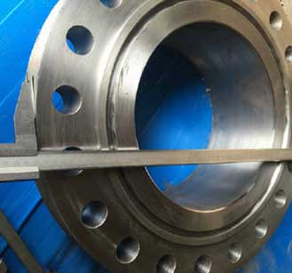
ASTM A694 F70 Flanges
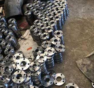
Carbon Steel A694 F70 Material
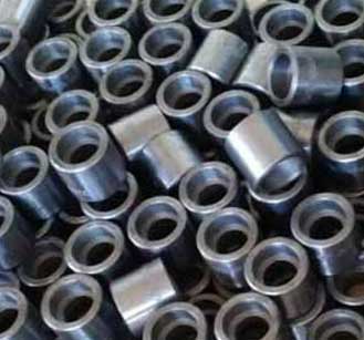
SA 694 F70 Forged Fittings
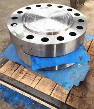
Carbon steel or alloy steel specified ASTM A694 components are often selected for their high yield capabilities in combination with its excellent toughness and weldability at low temperature.
These high yield SA 694 F70 Forged Fittings not only perform well under high pressure, but the cost of production is much lower than stainless steel alloys or alloy steel grades, due to carbon steels using only 2 alloys. Overall, the excellent performance, along with good strength and toughness and cost is what makes the ASTM A694 Gr F70 Forged Flanges very attractive to many buyers across different industries.
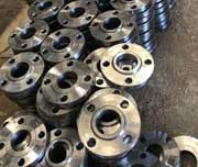
A694 CS Gr F70 Socket Weld Flanges
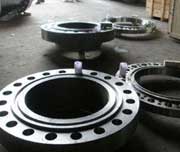
Grade F70 Carbon Steel Slip On Flanges
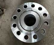
High Yield Carbon Steel F70 RTJ Flanges
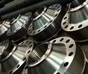
Steel Grade F70 Raised Face Flanges
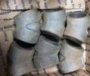
Carbon Steel A694 F70 90 Deg Elbow
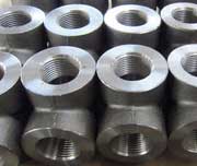
Carbon Steel ASME SA694 F70 Socket Weld Tee
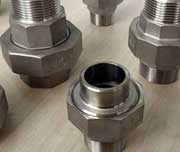
ASME SA 694 F70 Threaded Union
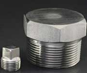
ASTM A694 F70 Steel Threaded Hex Plug
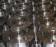
SA 694 F70 Blind Flanges
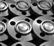
Carbon Steel A694 Grade F70 Flat Face Flanges
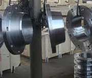
ASTM A694 Gr F70 Reducing Flanges
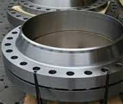
A694 F70 Weld Neck Flanges
| Specification : | ASTM A694 F70 Flanges |
| Size Chart : | 1/2″ (15 NB) To 48″ (1200NB) |
| Coating Flange Faces : | Cold and Hot Dip Galvanized, Oil Black Paint, Zinc Plated, Yellow Transparent, Anti-rust Paint |
| Forged Type : | NPT (Threaded), BSPT, BSPP. |
| Pressure Rating Table: | Class 150 LBS, Class 300 LBS, Class 600 LBS, Class 900 LBS, Class 1500 LBS, Class 2500 LBS |
| Standards: | EN-1092 Flanges, BS10 Flanges, MSS SP44 Flanges, ASME B16.5 Flanges, ASME B16.47 (Series A, Series B) GOST Flanges, DIN Flanges, PN Flanges, JIS Flanges, ISO Flanges, UNI Flanges, AWWA Flanges, ASME B16.38 Flanges |
| Dimensions Class: | 2000#, 3000#, 6000#, 9000# |
| Design For Size: | BS, PN, EN, ASA, ASME, DIN, JIS, ANSI |
| Production Process: | Forged, Heat Treated, Machined |
| Flange Machining Equipment: | electric bevelling machine, Bending machine, Pushing Machine, Press machine, Sand-blasting machine etc |
| Application: | Nuclear Power Plant Water Pipeline Industry Natural Gas Industry Oil And Gas Industry Fabrication Industry Chemical Industry |
NPS |
Flange (ID) (inch) |
Flange (OD) (inch) |
||||
| 150LB | 300LB | 400LB | 600LB | 900LB | ||
| 1/2 | 0.84 | 1.875 | 2.125 | 2.125 | 2.125 | 2.50 |
| 3/4 | 1.06 | 2.25 | 2.625 | 2.625 | 2.625 | 2.75 |
| 1 | 1.31 | 2.625 | 2.875 | 2.875 | 2.875 | 3.125 |
| 1 1/4 | 1.66 | 3 | 3.25 | 3.25 | 3.25 | 3.50 |
| 1 1/2 | 1.91 | 3.375 | 3.75 | 3.75 | 3.75 | 3.875 |
| 2 | 2.38 | 4.125 | 4.375 | 4.375 | 4.375 | 5.625 |
| 2 1/2 | 2.88 | 4.875 | 5.125 | 5.125 | 5.125 | 6.50 |
| 3 | 3.50 | 5.375 | 5.875 | 5.875 | 5.875 | 6.625 |
| 4 | 4.50 | 6.875 | 7.125 | 7.00 | 7.625 | 8.125 |
| 5 | 5.56 | 7.75 | 8.50 | 8.375 | 9.50 | 9.75 |
| 6 | 6.62 | 8.75 | 9.875 | 9.75 | 10.50 | 11.375 |
| 8 | 8.62 | 11 | 12.125 | 12.00 | 12.625 | 14.125 |
| 10 | 10.75 | 13.375 | 14.25 | 14.125 | 15.75 | 17.125 |
| 12 | 12.75 | 16.125 | 16.625 | 16.50 | 18.00 | 19.625 |
| Gr | C | Mn | P | S | Si |
| ASME SA 694 F70 | 0.26-0.265 | 1.60-1.64 | 0.025-0.030 | 0.025-0.030 | 0.15-0.35 |
| Element | Tensile Strength | Yield Strength (0.2%Offset) | Elongation |
| Carbon Steel A694 Grade F70 | 415 | 450 | 20 % |
| Standard | Class | Di. | Bolt Circle Dia. | No. of Bolts | Bolt Size | Dia. of Bolt Hole |
|---|---|---|---|---|---|---|
| AS4087 | PN14 | 95 | 67 | 4 | M12 | 14 |
| 2129 Flange | Table C | 95 | 67 | 4 | 13 | 14 |
| Table D | 95 | 67 | 4 | 13 | 14 | |
| Table E | 95 | 67 | 4 | 13 | 14 | |
| Table F | 95 | 67 | 4 | 13 | 14 | |
| Table H | 114 | 83 | 4 | 16 | 17 | |
| Table J | 114 | 83 | 4 | 16 | 17 | |
| ASI B16.5 Flanges | ANSI 150 | 89 | 60 | 4 | 13 | 16 |
| ANSI 300 | 95 | 67 | 4 | 13 | 16 | |
| ANSI 600 | 95 | 67 | 4 | 13 | 16 | |
| ANSI 900 | 121 | 83 | 4 | 19 | 22 | |
| ANSI 1500 | 121 | 83 | 4 | 19 | 22 | |
| ISO 7005 (DIN) Flange | PN6 | 80 | 55 | 4 | M10 | 11 |
| PN10 | 95 | 65 | 4 | M12 | 14 | |
| PN16 | 95 | 65 | 4 | M12 | 14 | |
| PN20 | 90 | 60.5 | 4 | M14 | 16 | |
| PN25 | 95 | 65 | 4 | M12 | 14 | |
| PN40 | 95 | 65 | 4 | M12 | 14 |
| Temp. °C | ASTM A694 F70 Flanges Working Pressure Range | ||||||
|---|---|---|---|---|---|---|---|
| Class 150 | Class 300 | Class 400 | Class 600 | Class 900 | Class 1500 | Class 2500 | |
| -29 ~ 38 | 19.6 | 51.1 | 68.1 | 102.1 | 153.2 | 255.3 | 425.5 |
| 50 | 19.2 | 50.1 | 66.8 | 100.2 | 150.4 | 250.6 | 417.7 |
| 100 | 17.7 | 46.6 | 62.1 | 93.2 | 139.8 | 233.0 | 388.3 |
| 150 | 15.8 | 45.1 | 60.1 | 90.2 | 135.2 | 225.4 | 375.6 |
| 200 | 13.8 | 43.8 | 58.4 | 87.6 | 131.4 | 219.0 | 365.0 |
| 250 | 12.1 | 41.9 | 55.9 | 83.9 | 125.8 | 209.7 | 349.5 |
| 300 | 10.2 | 39.8 | 53.1 | 79.6 | 119.5 | 199.1 | 331.8 |
| 325 | 9.3 | 38.7 | 51.6 | 77.4 | 116.1 | 193.6 | 322.6 |
| 350 | 8.4 | 37.6 | 50.1 | 75.1 | 112.7 | 187.8 | 313.0 |
| 375 | 7.4 | 36.4 | 48.5 | 72.7 | 109.1 | 181.8 | 303.1 |
| 400 | 6.5 | 34.7 | 46.3 | 69.4 | 104.2 | 173.6 | 289.3 |
| 425 | 5.5 | 28.8 | 38.4 | 57.5 | 86.3 | 143.8 | 239.7 |
| 450 | 4.6 | 23.0 | 30.7 | 46.0 | 69.0 | 115.0 | 191.7 |
| 475 | 3.7 | 17.4 | 23.2 | 34.9 | 52.3 | 87.2 | 145.3 |
| 500 | 2.8 | 11.8 | 15.7 | 23.5 | 35.3 | 58.8 | 97.9 |
| 538 | 1.4 | 5.9 | 7.9 | 11.8 | 17.7 | 29.5 | 49.2 |