-
-
send us mail
[email protected]
Generally, the specified ASTM A694 F60 Flanges are to be subjected to a chemical heat analysis. On the other hand, fittings produced under standard ANSI B16.11 and ASME B16.5 are required to be produced in accordance with the following parameters pressure-temperature ratings, materials, dimensions, tolerances, marking, testing, and methods of designating openings. These parameters are intended to be used in the manufacture of forged products such as the ANSI B16.11 A694 Gr F60 Elbow. Using a forging process on these components results in a directional grain flow. Which is why the mechanical and metallurgical properties of an ASTM A694 F60 Forged Fitting tend to be much better in comparison to any other process. The structural integrity of a forged fitting or a flange cannot be beaten by any other transformation process.
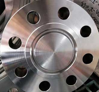
ASTM A694 F60 Flanges
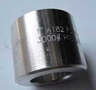
A694 F60 Forged Fitting
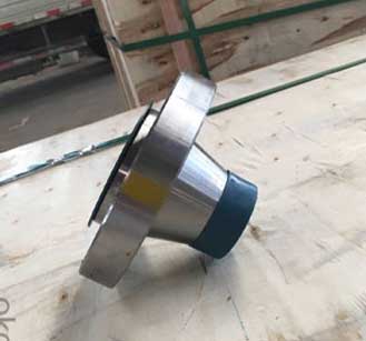
SA694 Gr F60 WNRF Flanges
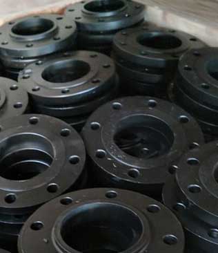
Like most ASTM flanges, the ASTM A694 components are required to adhere to the chemistry along with testing requirements and tensile property requirements as well.
| Chemical Composition | |
|---|---|
| Carbon [C] | ≤0.30 |
| Manganese [Mn] | ≤1.60 |
| Phosphorus [P] | ≤0.025 |
| Sulfur [S] | ≤0.025 |
| Silicon [Si] | 0.15-0.35 |
Since forging these components removes any form of porosities, gases and internal cavities there would be a reduction in the unexpected faults of ASME B16.5 A694 Gr F60 WNRF Flanges under stress, fatigue and impact. Lap joint flanges or as also referred to as loose flanges have a corresponding stub-end that that could be inserted in the inside of the flange. The main benefit of the Carbon Steel A694 Grade F60 Loose Flanges is that once the pipe has been welded to the insert stub-end, the flange is then able to rotate to create an easier alignment of the bolting holes. Blind flanges are used to seal off a valve in a piping system, thus the Carbon Steel A694 Grade F60 BLRF Flanges prove to be a leaf-poof solution for piping systems.
| Specification : | ASTM A694 F60 Flanges |
| Design For Size: | BS, PN, EN, ASA, ASME, DIN, JIS, ANSI |
| Flange Machining Equipment: | electric bevelling machine, Bending machine, Pushing Machine, Press machine, Sand-blasting machine etc |
| Size Chart : | 1/2″ (15 NB) To 48″ (1200NB) |
| Coating Flange Faces : | Cold and Hot Dip Galvanized, Zinc Plated, Yellow Transparent, Oil Black Paint, Anti-rust Paint |
| Dimensions Class: | 2000#, 3000#, 6000#, 9000# |
| Forged Type : | NPT (Threaded), BSPT, BSPP. |
| Pressure Rating Table: | Class 150 LBS, Class 300 LBS, Class 600 LBS, Class 900 LBS, Class 1500 LBS, Class 2500 LBS |
| Standards: | ASME B16.38 Flanges, EN-1092 Flanges, BS10 Flanges, DIN Flanges, PN Flanges, JIS Flanges, ISO Flanges, UNI Flanges, AWWA Flanges, MSS SP44 Flanges, ASME B16.5 Flanges, ASME B16.47 (Series A, Series B), GOST Flanges |
| Production Process: | Machined, Forged, Heat Treated |
| Application: | Natural Gas Industry Fabrication Industry Chemical Industry Nuclear Power Plant Water Pipeline Industry Oil And Gas Industry |
| Element | Tensile Strength | Yield Strength (0.2%Offset) | Elongation |
| Carbon Steel F60 | 515 | 415 | 20 % |
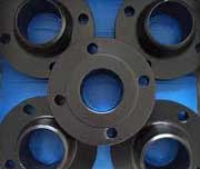
A694 CS Gr F60 Socket Weld Flanges
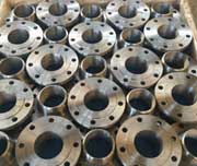
Grade F60 Carbon Steel Slip On Flanges
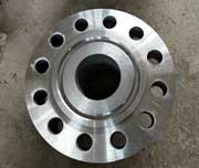
High Yield Carbon Steel F60 RTJ Flanges
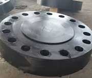
Steel Grade F60 Raised Face Flanges
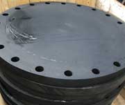
SA 694 F60 Blind Flanges
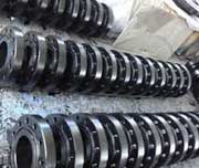
Carbon Steel A694 Grade F60 Flat Face Flanges
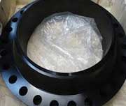
ASTM A694 Gr F60 Reducing Flanges
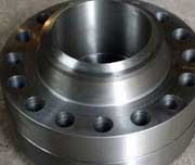
A694 F60 Weld Neck Flanges
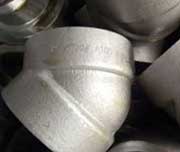
Carbon Steel A694 F60 90 Deg Elbow
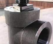
Carbon Steel ASME SA694 F60 Socket Weld Tee
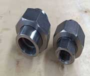
ASME SA 694 F60 Threaded Union
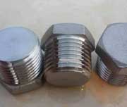
ASTM A694 F60 Steel Threaded Hex Plug
| Curie temperature | 770 °C at 20 °C | Typical for Low Carbon Steel |
| Coefficient of thermal expansion | 1.32E-5 - 1.38E-5 1/K at 20 °C | Typical for Low CS |
| Max service temperature | 500 °C | Typical for CS |
| Melting point | 1480 - 1526 °C | Typical for Low CS |
| Temp. °C | ASTM A694 F60 Flanges Working Pressure Range | ||||||
|---|---|---|---|---|---|---|---|
| 150 | 300 | 400 | 600 | 900 | 1500 | 2500 | |
| -29 ~ 38 | 19.6 | 51.1 | 68.1 | 102.1 | 153.2 | 255.3 | 425.5 |
| 50 | 19.2 | 50.1 | 66.8 | 100.2 | 150.4 | 250.6 | 417.7 |
| 100 | 17.7 | 46.6 | 62.1 | 93.2 | 139.8 | 233.0 | 388.3 |
| 150 | 15.8 | 45.1 | 60.1 | 90.2 | 135.2 | 225.4 | 375.6 |
| 200 | 13.8 | 43.8 | 58.4 | 87.6 | 131.4 | 219.0 | 365.0 |
| 250 | 12.1 | 41.9 | 55.9 | 83.9 | 125.8 | 209.7 | 349.5 |
| 300 | 10.2 | 39.8 | 53.1 | 79.6 | 119.5 | 199.1 | 331.8 |
| 325 | 9.3 | 38.7 | 51.6 | 77.4 | 116.1 | 193.6 | 322.6 |
| 350 | 8.4 | 37.6 | 50.1 | 75.1 | 112.7 | 187.8 | 313.0 |
| 375 | 7.4 | 36.4 | 48.5 | 72.7 | 109.1 | 181.8 | 303.1 |
| 400 | 6.5 | 34.7 | 46.3 | 69.4 | 104.2 | 173.6 | 289.3 |
| 425 | 5.5 | 28.8 | 38.4 | 57.5 | 86.3 | 143.8 | 239.7 |
| 450 | 4.6 | 23.0 | 30.7 | 46.0 | 69.0 | 115.0 | 191.7 |
| 475 | 3.7 | 17.4 | 23.2 | 34.9 | 52.3 | 87.2 | 145.3 |
| 500 | 2.8 | 11.8 | 15.7 | 23.5 | 35.3 | 58.8 | 97.9 |
| 538 | 1.4 | 5.9 | 7.9 | 11.8 | 17.7 | 29.5 | 49.2 |
NPS |
Flanges (ID) (inch) |
Flanges (OD) (inch) |
||||
| 150# | 300# | 400# | 600# | 900# | ||
| 1/2 | 0.84 | 1.875 | 2.125 | 2.125 | 2.125 | 2.50 |
| 3/4 | 1.06 | 2.25 | 2.625 | 2.625 | 2.625 | 2.75 |
| 1 | 1.31 | 2.625 | 2.875 | 2.875 | 2.875 | 3.125 |
| 1 1/4 | 1.66 | 3 | 3.25 | 3.25 | 3.25 | 3.50 |
| 1 1/2 | 1.91 | 3.375 | 3.75 | 3.75 | 3.75 | 3.875 |
| 2 | 2.38 | 4.125 | 4.375 | 4.375 | 4.375 | 5.625 |
| 2 1/2 | 2.88 | 4.875 | 5.125 | 5.125 | 5.125 | 6.50 |
| 3 | 3.50 | 5.375 | 5.875 | 5.875 | 5.875 | 6.625 |
| 4 | 4.50 | 6.875 | 7.125 | 7.00 | 7.625 | 8.125 |
| 5 | 5.56 | 7.75 | 8.50 | 8.375 | 9.50 | 9.75 |
| 6 | 6.62 | 8.75 | 9.875 | 9.75 | 10.50 | 11.375 |
| 8 | 8.62 | 11 | 12.125 | 12.00 | 12.625 | 14.125 |
| 10 | 10.75 | 13.375 | 14.25 | 14.125 | 15.75 | 17.125 |
| 12 | 12.75 | 16.125 | 16.625 | 16.50 | 18.00 | 19.625 |
| Standard | Class | Di. | Bolt Circle Dia. | No. of Bolts | Bolt Size | Dia. of Bolt Hole |
|---|---|---|---|---|---|---|
| AS4087 | PN14 | 95 | 67 | 4 | M12 | 14 |
| 2129 Flange | Table C | 95 | 67 | 4 | 13 | 14 |
| Table D | 95 | 67 | 4 | 13 | 14 | |
| Table E | 95 | 67 | 4 | 13 | 14 | |
| Table F | 95 | 67 | 4 | 13 | 14 | |
| Table H | 114 | 83 | 4 | 16 | 17 | |
| Table J | 114 | 83 | 4 | 16 | 17 | |
| ASME B16.5 Flanges | ANSI 150 | 89 | 60 | 4 | 13 | 16 |
| ANSI 300 | 95 | 67 | 4 | 13 | 16 | |
| ANSI 600 | 95 | 67 | 4 | 13 | 16 | |
| ANSI 900 | 121 | 83 | 4 | 19 | 22 | |
| ANSI 1500 | 121 | 83 | 4 | 19 | 22 | |
| ISO 7005 (DIN) Flange | PN6 | 80 | 55 | 4 | M10 | 11 |
| PN10 | 95 | 65 | 4 | M12 | 14 | |
| PN16 | 95 | 65 | 4 | M12 | 14 | |
| PN20 | 90 | 60.5 | 4 | M14 | 16 | |
| PN25 | 95 | 65 | 4 | M12 | 14 | |
| PN40 | 95 | 65 | 4 | M12 | 14 |